Systems

Coaxial Electric Rotors: Disk Area, Wake Interaction and Hover Power

Why eight rotors can mean four projected disks—and how coaxial wake interaction changes the interpretation of hover power, counter-rotation and motor-out claims.
October 27, 2026

·
5 min
· By PropulsionWatch Editorial
Coaxial Electric Rotors: Disk Area, Wake Interaction and Hover Power

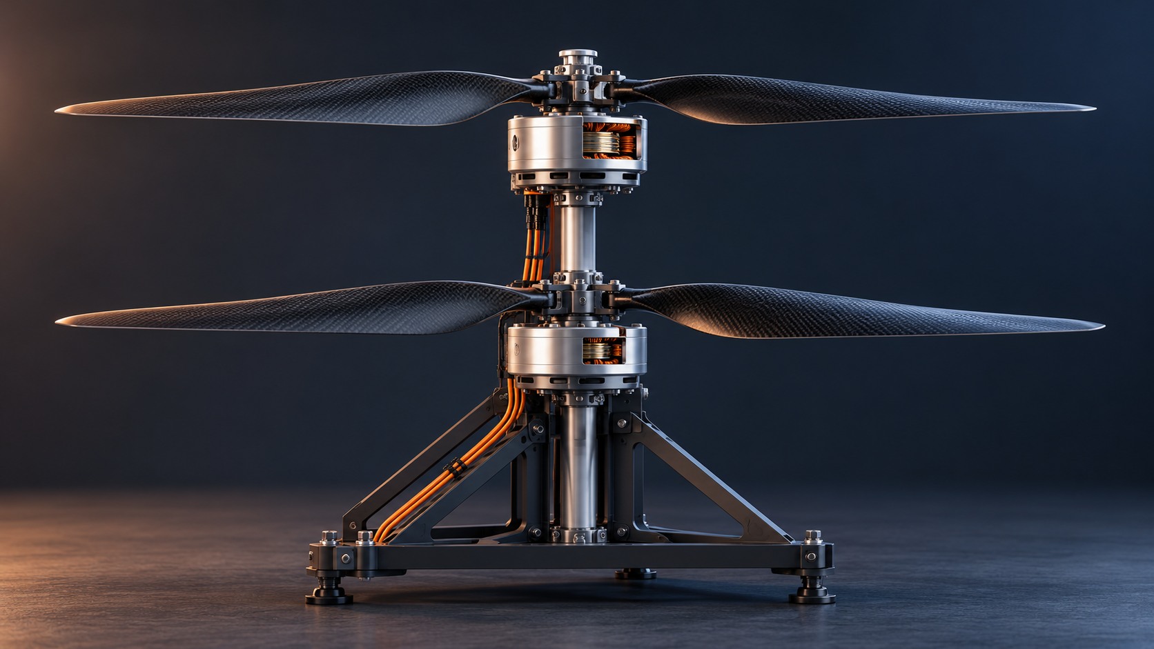
Eight electric motors can drive eight rotors while providing only four distinct projected rotor disks. A coaxial arrangement puts one rotor above another on the same axis. It saves lateral space, but changes how the rotors share the airflow. Counting motors alone tells us little about hover efficiency.

Jetson ONE is a useful configuration example: official photographs show four coaxial pairs on an open single-seat multicopter. The explanation below concerns the architecture. It does not calculate Jetson's power demand, endurance or safety margins.

Start with disk area, not motor count

The projected area of an equal-radius coaxial pair is approximately one circle, A = πr². Adding a second rotor above it does not create a second, separate column of undisturbed air. Two separated rotors of the same radius can occupy a combined projected area of 2πr², assuming no overlap.

The compact arrangement therefore trades footprint against aerodynamic design freedom. The relevant comparison must specify radius, total thrust, separation, loading and installation constraints. Comparing the same number of motors without those assumptions can produce a misleading efficiency claim.
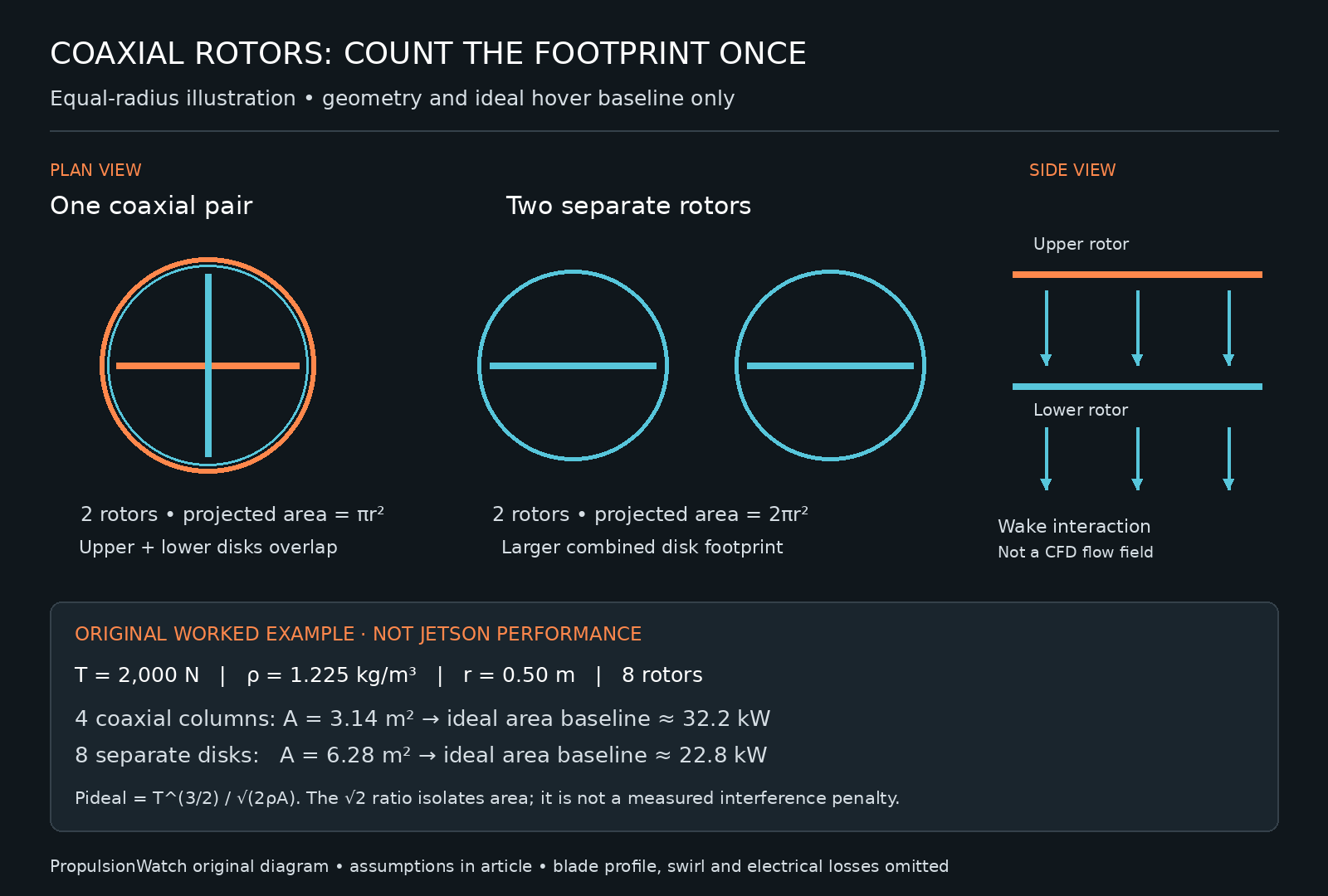
Original diagram comparing one coaxial pair with two separate disks, showing wake interaction and an ideal hover area calculation.
PropulsionWatch original diagram. Equal-radius geometry and an illustrative ideal-power baseline; not a measured aircraft result or CFD flow field.

A calculation that isolates the area effect

For an ideal actuator disk in hover, a useful reference is Pideal = T3/2 / √(2ρA), where T is total thrust, ρ is air density and A is disk area. This is an ideal induced-power baseline: blade profile drag, wake nonuniformity, swirl and electrical losses are omitted. A real coaxial system requires additional modelling.

Take an original toy example with eight rotors, each radius 0.50 m, producing 2,000 N total thrust in air at 1.225 kg/m³. Arrange them as four coaxial columns and the combined projected area is 3.14 m². Put all eight disks apart and it becomes 6.28 m².

Applying the same ideal area baseline gives approximately 32.2 kW for the smaller footprint and 22.8 kW for the larger one. The ratio is √2. These are not predicted shaft powers, a measured coaxial interference penalty or Jetson performance figures. The exercise changes available area while deliberately leaving out the difficult interaction physics.

The lower rotor does not see the same inflow

The upper rotor accelerates the air before it reaches the lower rotor. Rotor spacing, blade loading, rotational direction and operating point influence that interaction. Counter-rotation can recover some rotational energy in the wake, but does not make the two rotors aerodynamically independent.

A NASA Ames study by Barbely, Komerath and Novak simulated coaxial hover and forward flight, examining pressure fields above, between and below the rotors at different blade azimuths. Its use of unsteady flow modelling is a reminder that a static motor diagram cannot describe the complete aerodynamic system.

For engineering assessment, ask for the tested rotor geometry and operating conditions behind an efficiency number. An isolated motor's efficiency map is not a coaxial rotor-system efficiency map. Installation losses and power electronics add further boundaries to the measurement.

Counter-rotation is also a control question

Opposite rotation can balance reaction torque when the pair is appropriately loaded. A change in relative thrust or torque changes that balance. Losing a motor also changes the airflow seen by the remaining rotor and the control authority available to the aircraft.

Chen and colleagues' NASA-hosted dynamic-inflow work discusses rotor interference and coupling with body dynamics in stability and control analysis. A control assessment therefore needs more than eight motor icons: it needs the coupled response of the rotors, airframe and controller.

Electrical independence is a separate question. Shared batteries, buses, cooling or protection devices may connect nominally separate motors. Conversely, good electrical segregation does not remove aerodynamic coupling. Neither motor count nor counter-rotation alone establishes a safe degraded-flight envelope.

What useful evidence looks like

  • Geometry: rotor diameter, axial spacing, blade shape and installation obstructions.
  • Performance: thrust and shaft/electrical power measured for the complete pair across operating points.
  • Control: response to thrust changes and representative degraded conditions, with stated mass and environment.
  • Measurement boundary: whether the quoted efficiency includes controller, motor, wiring and rotor losses.

The value of a coaxial layout is compactness with a particular set of aerodynamic and control trade-offs. A meaningful aircraft comparison keeps those trade-offs visible instead of treating overlapping disks as isolated rotors.

Related: redundancy beyond rotor count and windmilling, braking torque and feathering.

Sources & evidence

  1. Jetson — official Jetson ONE configuration and imagery, reviewed 27 October 2026. Manufacturer reference, not an independent aerodynamic assessment.
  2. Barbely, Komerath and Novak — A Study of Coaxial Rotor Performance and Flow Field Characteristics, 20 January 2016.
  3. Chen et al. — Extraction of Dynamic Inflow Models for Coaxial and Tandem Rotors from CFD Simulations, 13 May 2019. Its cited tandem-rotor percentage is not used as a coaxial penalty.
  4. Johnson — Influence of Lift Offset on Rotorcraft Performance, NASA/TP-2009-215404, 1 November 2009. Rotorcraft theory context; not a Jetson test report.

Imagery: text-free hero is a PropulsionWatch AI-generated conceptual illustration, not a manufacturer product or installation. The in-article diagram and worked calculation are original explanatory material with the assumptions stated above.

Two quick questions before you go.

Which of these best describes you?
What would make PropulsionWatch most useful to you next?
Thanks — this helps shape what PropulsionWatch builds next.
Oops! Something went wrong while submitting the form.
View all
Blown Lift: How Propulsion Power Changes Wing Lift and Landing Margins
Systems

Blown Lift: How Propulsion Power Changes Wing Lift and Landing Margins

October 26, 2026

·
5 min
When an Electric Aircraft Motor Fails: Windmilling, Braking Torque and Feathering
Systems

When an Electric Aircraft Motor Fails: Windmilling, Braking Torque and Feathering

October 22, 2026

·
5 min
Hybrid-Electric Aircraft Power Management: The Generator, Battery and Reserve
Systems

Hybrid-Electric Aircraft Power Management: The Generator, Battery and Reserve

October 19, 2026

·
5 min
eVTOL Landing Reserves: Why State of Charge Is Not Enough
Systems

eVTOL Landing Reserves: Why State of Charge Is Not Enough

October 19, 2026

·
5 min
Electromagnetic Interference in Electric Aircraft: From Inverter Switching to Avionics Upsets
Systems

Electromagnetic Interference in Electric Aircraft: From Inverter Switching to Avionics Upsets

October 17, 2026

·
7 min
Lightning Protection for Electric Aircraft: Composite Structure, HV Batteries and Distributed Propulsion
Systems

Lightning Protection for Electric Aircraft: Composite Structure, HV Batteries and Distributed Propulsion

September 25, 2026

·
6 min
When the Motor Is the Flight-Control Actuator: Propulsion Bandwidth in eVTOL
Systems

When the Motor Is the Flight-Control Actuator: Propulsion Bandwidth in eVTOL

8 min
How an eVTOL High-Voltage Bus Fails: Shorts, Series Arcs and Fault Clearing
Systems

How an eVTOL High-Voltage Bus Fails: Shorts, Series Arcs and Fault Clearing

8 min
Where eVTOL Rotor Noise Comes From: Tip Speed, Blade-Passing Tones and Rotor Interaction
Systems

Where eVTOL Rotor Noise Comes From: Tip Speed, Blade-Passing Tones and Rotor Interaction

8 min
eVTOL Thermal Management Is a Mission Problem, Not a Cooling-Loop Problem
Systems

eVTOL Thermal Management Is a Mission Problem, Not a Cooling-Loop Problem

9 min
High Voltage at Altitude: The Insulation Problem Inside eVTOL Powertrains
Systems

High Voltage at Altitude: The Insulation Problem Inside eVTOL Powertrains

8 min
Vertiport Engineering: Where Aircraft Architecture Meets Infrastructure
Systems

Vertiport Engineering: Where Aircraft Architecture Meets Infrastructure

10 min
Geared vs. Direct-Drive Electric Propulsion: The Aircraft-Level Trade
Systems

Geared vs. Direct-Drive Electric Propulsion: The Aircraft-Level Trade

7 min
Distributed Electric Propulsion: Redundancy Beyond Rotor Count
Systems

Distributed Electric Propulsion: Redundancy Beyond Rotor Count

6 min
eVTOL Battery Cycle Life: From Laboratory Counts to Fleet Life
Systems

eVTOL Battery Cycle Life: From Laboratory Counts to Fleet Life

6 min
No Single Motor Does the Work: How eVTOL Power Is Actually Distributed
Systems

No Single Motor Does the Work: How eVTOL Power Is Actually Distributed

5 min
eVTOL Batteries: Cell Energy, Pack Mass and Safety Margins
Systems

eVTOL Batteries: Cell Energy, Pack Mass and Safety Margins

August 11, 2026

·
12 min
eVTOL Inverters and Motor Controllers: Power Density, Heat and Fault Tolerance
Systems

eVTOL Inverters and Motor Controllers: Power Density, Heat and Fault Tolerance

August 11, 2026

·
9 min
Axial-Flux vs. Radial-Flux Motors: The Aircraft-Level Trade
Systems

Axial-Flux vs. Radial-Flux Motors: The Aircraft-Level Trade

August 11, 2026

·
6 min
eVTOL Battery Thermal Runaway: Cell Propagation and Containment
Systems

eVTOL Battery Thermal Runaway: Cell Propagation and Containment

5 min
Multicopter, Lift + Cruise and Vectored Thrust: eVTOL Architecture Trade-offs
Systems

Multicopter, Lift + Cruise and Vectored Thrust: eVTOL Architecture Trade-offs

5 min