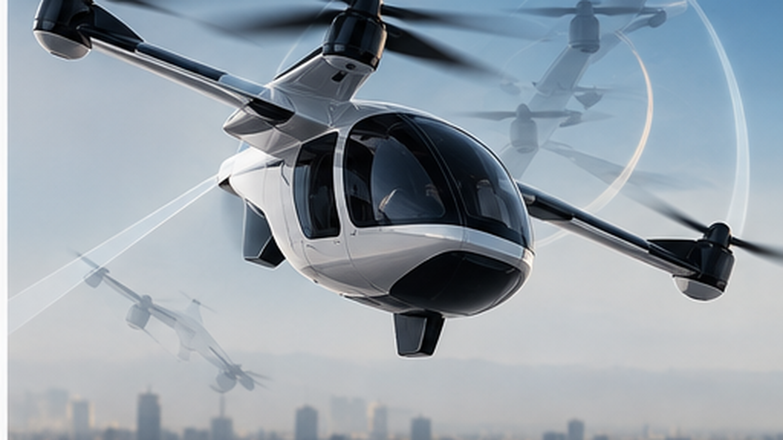
Carbon-fibre airframes, floating high-voltage batteries and many boom-mounted motors make lightning an architecture problem for eVTOL and electric aircraft. This explainer covers zoning, direct and indirect effects, rotor and bearing current paths, HV-bus transients and why a strike is a common-cause event for distributed propulsion.
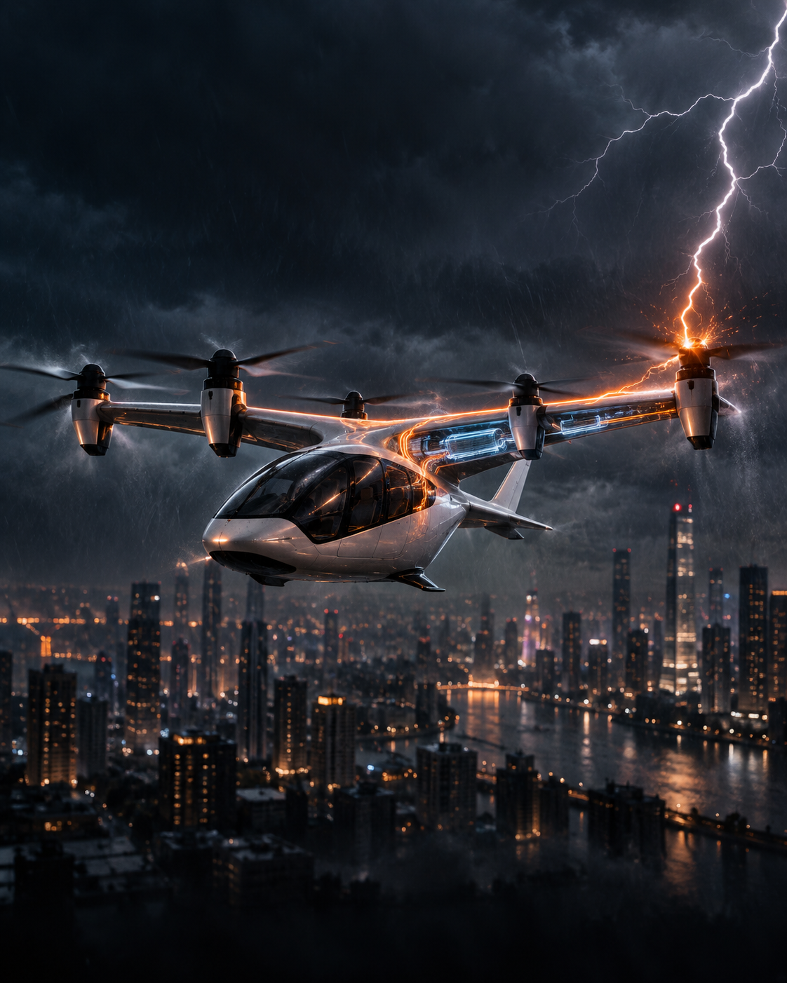
Every airliner in service is struck by lightning roughly once a year, according to Airbus' Safety First review of lightning strikes. Most of those strikes are triggered by the aircraft itself: its extremities launch leaders into a charged cloud and the airframe becomes part of the discharge channel. A metal airliner handles this by letting the current run along its skin. An electric aircraft is harder to protect. It has a carbon-fibre structure that conducts poorly, a high-voltage battery that floats relative to that structure, and many motors, inverters and flight-control lanes connected by long cable runs.
The FAA updated its main guidance on protecting electrical systems from lightning in May 2026, with AC 20-136C. It is a good moment to look at why lightning is an architecture problem for eVTOL and electric aircraft, and not just a coating problem.
The design environment comes from SAE ARP5412. Its severe first return stroke, Component A, peaks at 200 kA. The ARP5412 waveform set then follows that stroke with an intermediate current and a long, lower-amplitude continuing current. The two types of damage are treated separately:
Where the arc can attach is set by lightning zoning (SAE ARP5414). Zone 1 surfaces take initial attachment, Zone 2 surfaces see the channel swept back across them as the aircraft moves, and Zone 3 carries conducted current between entry and exit. Airbus notes that entry typically occurs at extremities such as the nose and wingtips, and exit at the rearmost parts of the aircraft.
Aluminium skin spreads strike current over a large, low-resistance surface. Carbon-fibre composite is far more resistive, and its resin matrix is an insulator. At the attachment point, the current density can exceed what the fibres can carry. The fibres vaporise, the resin pyrolyses and the laminate delaminates. The damage Airbus lists for composite structures follows directly: skin punctures, fibre tufting and delamination, and loss of the protective mesh.
The standard answer is a sacrificial conductive layer, usually expanded copper or aluminium foil co-cured into the outer ply. It carries the current across the surface and controls the size of the damage area. The mesh has to be continuous across panel joints and fastener lines, and bonded into a deliberate current-return path. Otherwise, current jumps to whatever conducts best, which is often a metal fitting, a hydraulic line or a cable shield.
Simulation work published in In Compliance Magazine shows how sharp this shift can be. When the outer structure is carbon composite, most of the strike current can move onto internal aluminium supports, and the magnetic fields around those paths couple into nearby wiring and motors.
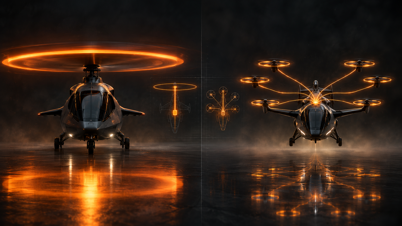
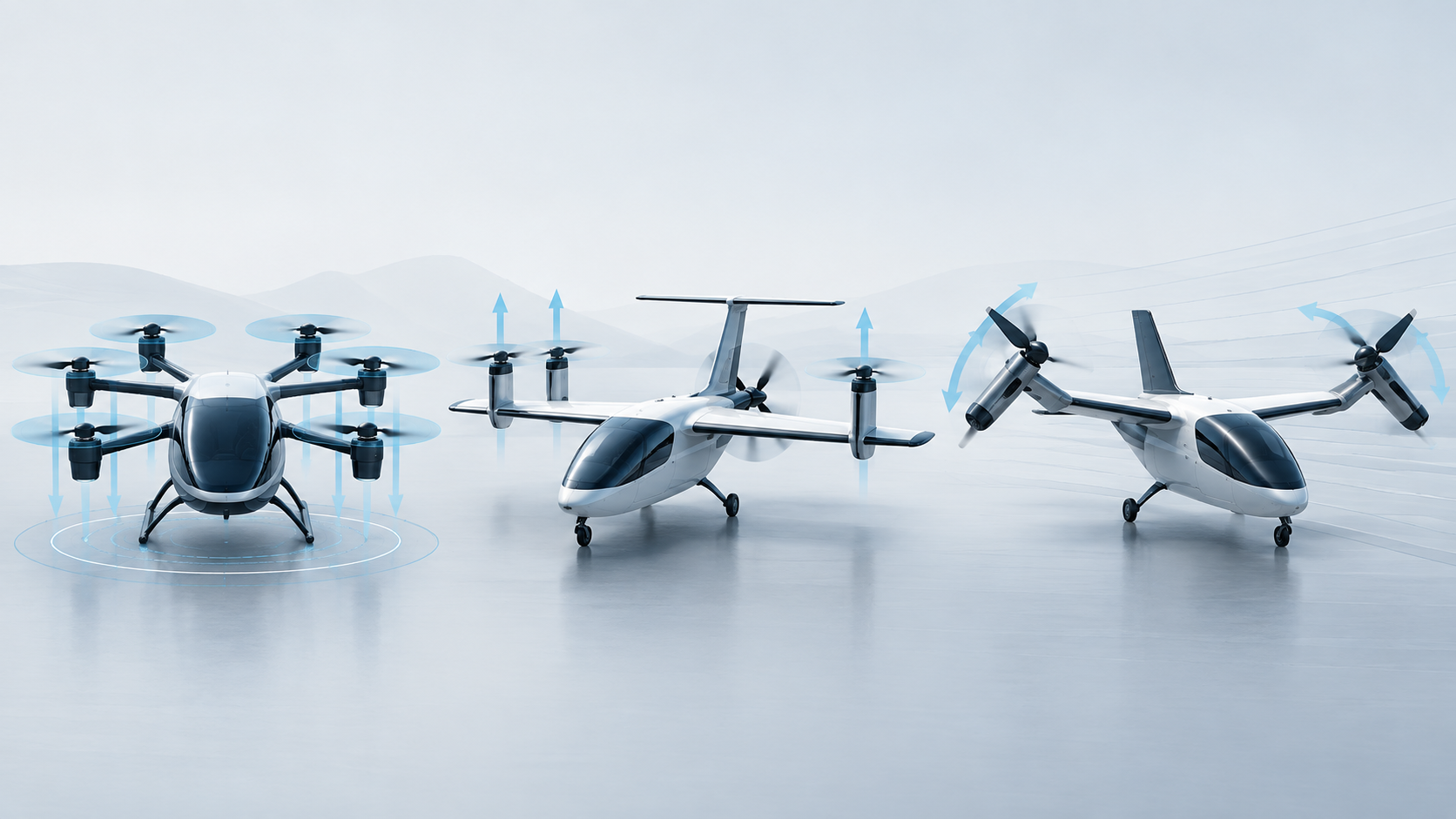
More attachment points, and zones that move. A conventional airplane has a handful of extremities. A distributed-propulsion eVTOL has rotor tips, boom ends, tail surfaces and nacelles spread across its span. On tilting designs, the geometry and therefore the zoning change between hover, transition and cruise. The zoning analysis has to cover every configuration in which the aircraft can meet a storm, not just one airframe shape.
Rotor blades are the most exposed parts. Composite propeller and rotor blades sit at the extremities and sweep through Zone 1 and Zone 2 regions. They need conductive leading-edge erosion shields or embedded diverters, connected to the hub. From there, the current has to reach the structure. The obvious path runs through the motor shaft, the bearings and the housing, and the same path matters for induced currents. Bearings are not designed to carry arc current, so a propulsion unit usually needs a defined bonding path that keeps strike current away from its bearings.
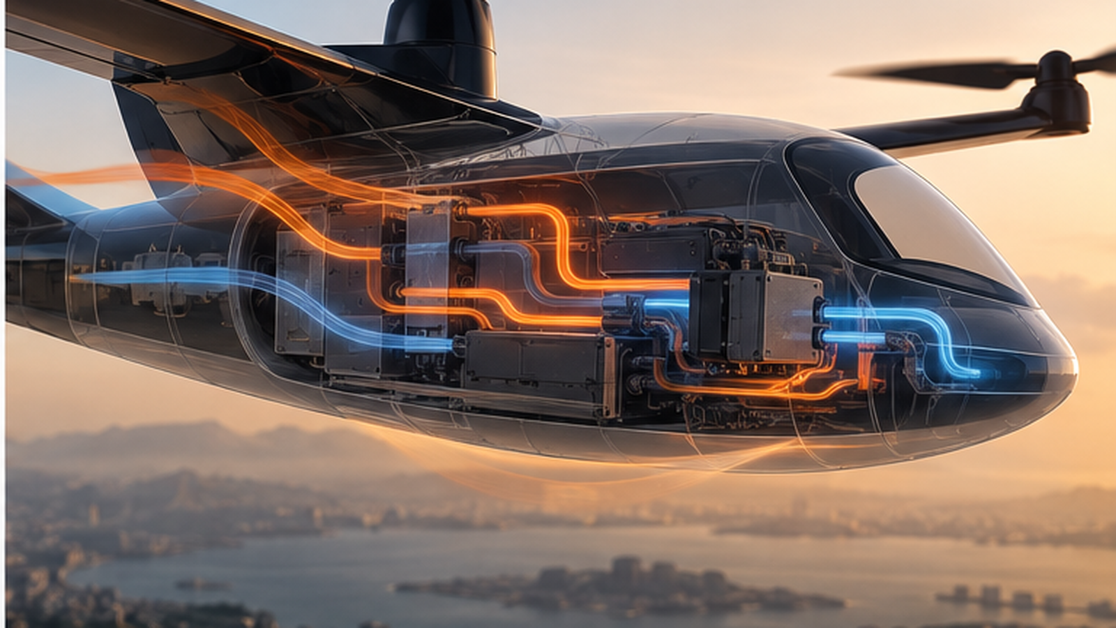
Long cables run through a weakly conducting structure. Every motor needs power and command cables running out along a boom or wing. Chen and co-authors modelled eVTOL indirect effects with the ARP5412 Component A waveform in a 2025 study in Electronics. Nose attachment produced the strongest coupling into the airframe. Induced current grew with cable length and depended on how the cable was routed. Shielded cables diverted most of the coupled current into the shield and away from the conductor. In a distributed architecture, that makes every boom-mounted propulsion unit a potential antenna.
An eVTOL propulsion battery is usually an isolated DC system. Neither pole is bonded to structure, and an insulation-monitoring device checks for leakage. Lightning current flowing through the structure shifts the potential of the airframe relative to that floating system. The result is a common-mode transient on the high-voltage feeders and across the insulation between the bus and structure. Two design choices meet here:
This is where the certification logic becomes demanding. Distributed propulsion earns its redundancy credit by assuming failures are independent. Lightning is the opposite: one event reaches every motor controller, every flight-control lane and every sensor at the same instant. Duplicating a controller does not help if both copies upset together.
The FAA's Part 23 requirement, 14 CFR 23.2515, applies to airplanes approved for IFR. It says systems whose failure would prevent continued safe flight and landing must not be adversely affected during and after lightning exposure. Systems whose failure would reduce the aircraft's capability or the crew's ability to respond must recover their function in a timely manner. For an eVTOL whose attitude control depends on motor torque, a controller that resets and recovers "in a timely manner" can still be too slow. As we covered in propulsion bandwidth and flight control, the motors are the flight-control actuators, so a short dropout across several lanes is a control event, not a nuisance. Powered-lift airworthiness criteria and EASA's SC-VTOL build on the same performance-based approach, so applicants have to show that the aircraft stays controllable through the strike itself, not just that it recovers afterwards.
Practical mitigations follow from that: separating the routing of redundant lanes, using shielded and twisted cable pairs with shields bonded at both ends, fitting transient protection at every box interface, and writing software that tolerates a short loss of data without latching a fault. None of this can be added late. Cable routing is fixed when the structure is designed.
Lightning protection costs mass in every place an eVTOL tries to save it: the surface mesh, a heavier current-return network, the shield braid on every propulsion cable, filters and surge suppression at each interface, and bonding hardware. Each item is small, but a distributed architecture multiplies them by the number of propulsion units. A protection scheme also needs test evidence: coupon and panel tests for direct effects, whole-aircraft or high-fidelity simulation for indirect effects, and DO-160 qualification for each equipment item. Designs that share cable runs or rely on structure for current return save weight up front but make the indirect-effects case harder to close.
Lightning rarely makes eVTOL headlines because it is resolved inside the certification basis, not at an air show. But it touches the areas that decide whether a design scales: composite structure, high-voltage insulation, motor bearings, flight-control redundancy and the cable weight of distributed propulsion. Programs that publish lightning test campaigns, or describe their current-return and cable-shielding approach, give the clearest signal that they have closed this part of the safety case. Whether a type certificate allows flight in known lightning conditions will also determine how usable these aircraft are in summer convective weather.