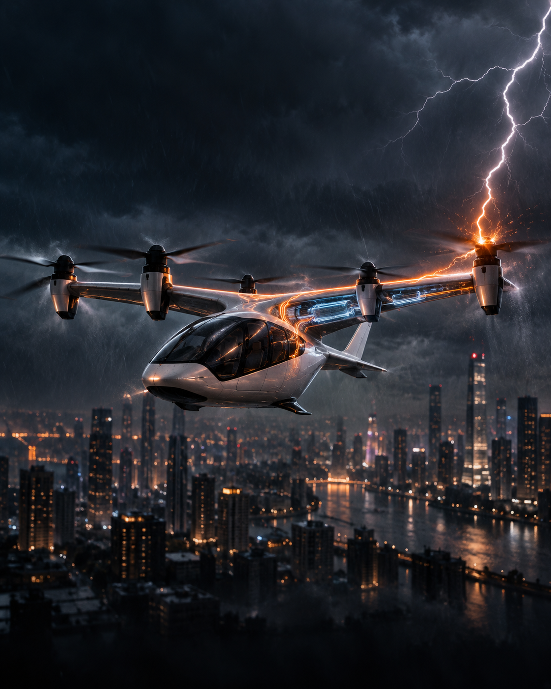
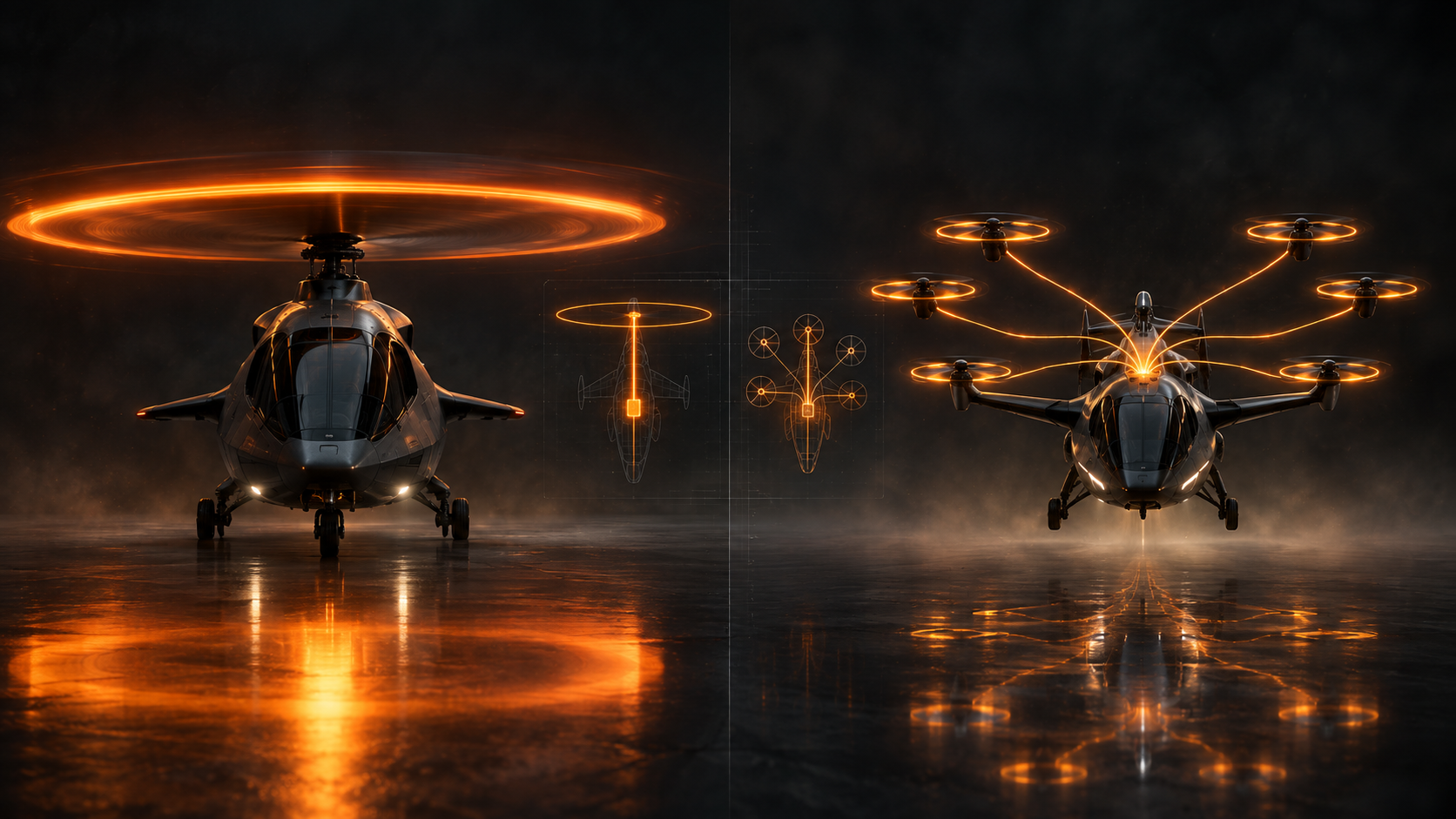
Higher DC-bus voltage can reduce current and conductor mass in electric aircraft, but it also raises the electric-field stress on motors, cables, connectors and power electronics. At altitude, partial discharge and insulation ageing become aircraft-level propulsion constraints rather than component details.
P = VI — higher voltage lowers current for a given transmitted power PDIV — partial-discharge inception voltage, a key insulation threshold 2024 — NASA/magniX altitude testing included partial-discharge measurements
Higher bus voltage can reduce conductor current and cable mass, but it raises the insulation-coordination burden across motors, cables, connectors and power electronics. Altitude, fast inverter edges and repeated thermal cycling make that trade aircraft-specific.
Altitude PD data, lifetime winding tests, connector and cable qualification after environmental ageing, and evidence that production propulsion systems retain adequate PD margin under representative inverter waveforms.
For a given electrical power, raising voltage reduces current: P = VI. That relationship is one reason electrified-aircraft designers are interested in higher-voltage distribution. Lower current can reduce conductor cross-section, resistive loss and the mass of cables feeding motors distributed around an airframe. The benefit is real, but it moves part of the propulsion problem into a less visible subsystem: electrical insulation.
An eVTOL powertrain does not operate in the same environment as an automotive traction system. Pressure changes with altitude, motors see repeated thermal excursions, inverter switching produces steep voltage edges, and the weight assigned to insulation, shielding, spacing and cooling is tightly constrained. The design objective is therefore not simply to prevent a dramatic flashover. It is to prevent progressive electrical damage over the aircraft's required life while retaining acceptable mass and thermal performance.
For a fixed conductor resistance, resistive heating follows Ploss = I²R. Doubling voltage for the same transmitted power halves current, which would reduce I²R loss by a factor of four if resistance stayed unchanged. In practice, engineers use some of that margin to reduce conductor size, so the aircraft-level result depends on cable length, allowable temperature rise, fault current, shielding and installation constraints.
The insulation system experiences the other side of the trade. Higher voltage increases the electric field across winding enamel, slot liners, potting compounds, connector gaps, busbar supports and cable insulation. Fast-switching inverters can add local overshoot and non-uniform voltage distribution, especially in motor windings. A nominal DC-bus value therefore does not fully describe the electrical stress seen by the first turns of a winding or at a geometric field concentration.
This is a useful extension to PropulsionWatch's inverter and motor-controller explainer: wide-bandgap switching can improve efficiency and power density, but the resulting voltage waveform becomes part of the insulation design.
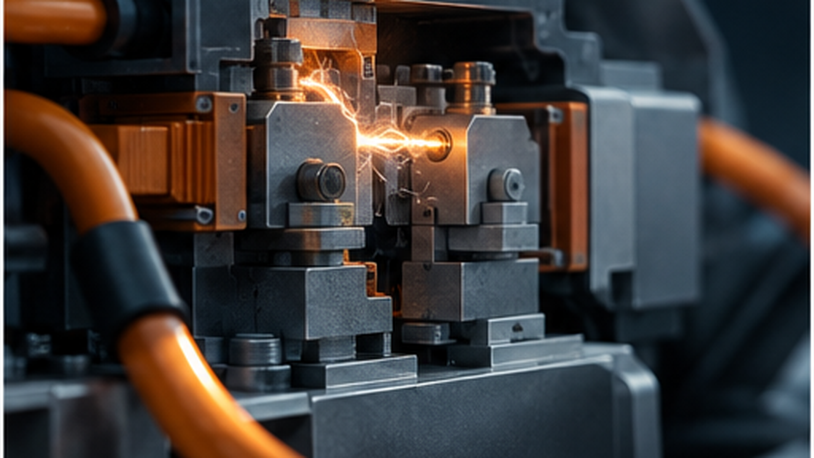
Partial discharge is a localized electrical discharge that bridges only part of the insulation between conductors. It can occur in microscopic voids, along interfaces or in gas-filled regions where the local electric field exceeds the dielectric strength of that region even though the complete insulation system has not failed.
The important threshold is often the partial-discharge inception voltage (PDIV). Operating below PDIV does not by itself guarantee unlimited insulation life, but operation above it can allow repeated discharge activity that erodes polymers, carbonizes surfaces and creates a path toward larger failures. That makes PDIV a design and health metric, not merely a laboratory curiosity.
NASA's electrified-aircraft insulation research treats this as an aviation problem because high voltage, thermal management and environmental conditions are coupled. In 2024, NASA and magniX used altitude testing to examine high-voltage propulsion hardware under reduced pressure and temperature, including partial-discharge behavior. The value of that work is the environment: insulation that behaves comfortably at sea-level laboratory pressure may have different margins when the aircraft climbs.
Electrical breakdown in gases depends on pressure, gap distance and field geometry. Reduced atmospheric pressure changes the conditions under which gas ionization and discharge can occur. The exact relationship is not captured by one universal voltage threshold because real aircraft installations contain non-uniform fields, solid-gas interfaces, contamination, manufacturing tolerances and transient waveforms.
That is why quoting an automotive bus voltage and adding an altitude derating factor is insufficient. Cable terminations, motor phase leads, connector cavities and unpotted regions can each have different local field concentrations. Clearance through air and creepage along an insulating surface are separate design quantities. Potting can suppress some gas gaps while introducing interfaces, thermal-expansion mismatch and repairability questions.
For propulsion systems mounted in nacelles or wings, pressure is only one variable. Moisture, contamination, vibration and temperature cycling can alter surface condition and mechanical fit over time. Certification evidence has to address the installed configuration and its foreseeable ageing, not only a pristine coupon.
Motor insulation is especially exposed because the winding has to carry high current, reject heat and survive repeated electromagnetic and mechanical loading. Random-wound machines contain many turns separated by thin enamel films. Inverter-fed voltage edges can concentrate stress between adjacent turns, while thermal cycling expands and contracts copper, resin and insulation materials at different rates.
A 2025 NASA study tracked PDIV in random-wound electric-aircraft motors after thermal cycling representative of an eVTOL application. The engineering point is broader than the result from one specimen set: propulsion insulation has a mission history. Hover, climb, cruise, descent and turnaround create repeated temperature cycles, and the insulation margin after hundreds or thousands of cycles is more relevant than the value measured on a new motor.
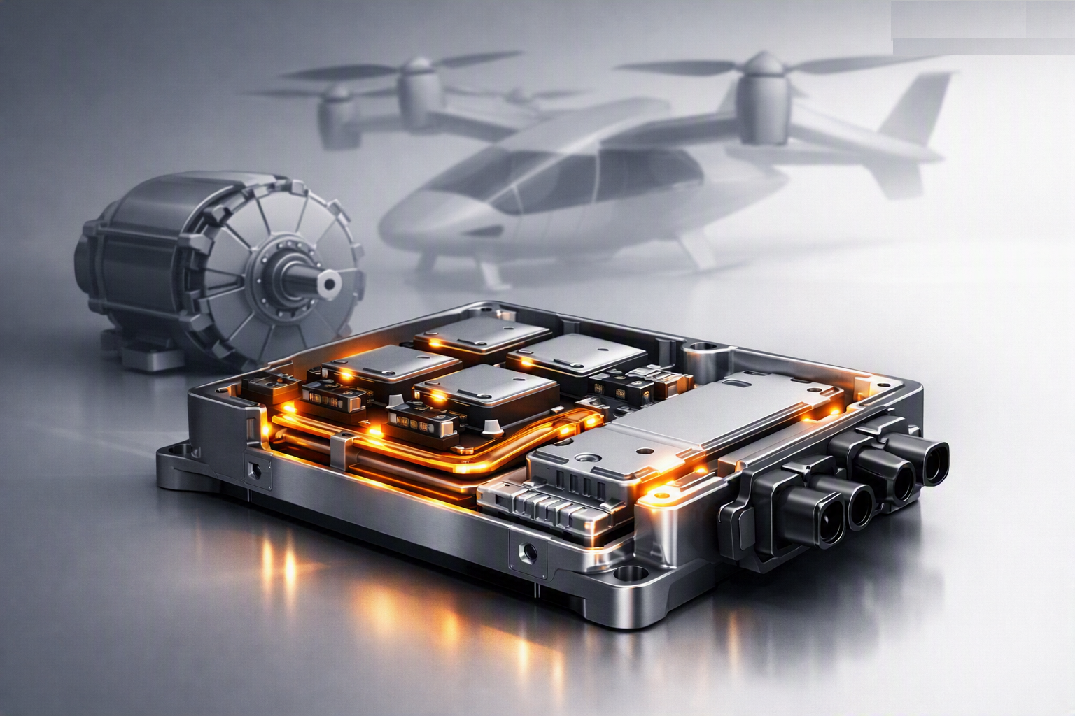
That also changes how motor power density should be read. A machine with excellent electromagnetic specific power may still need additional insulation thickness, thermal path material, spacing or filtering to achieve the required voltage and life. Those additions can change slot fill, heat transfer and installed mass.
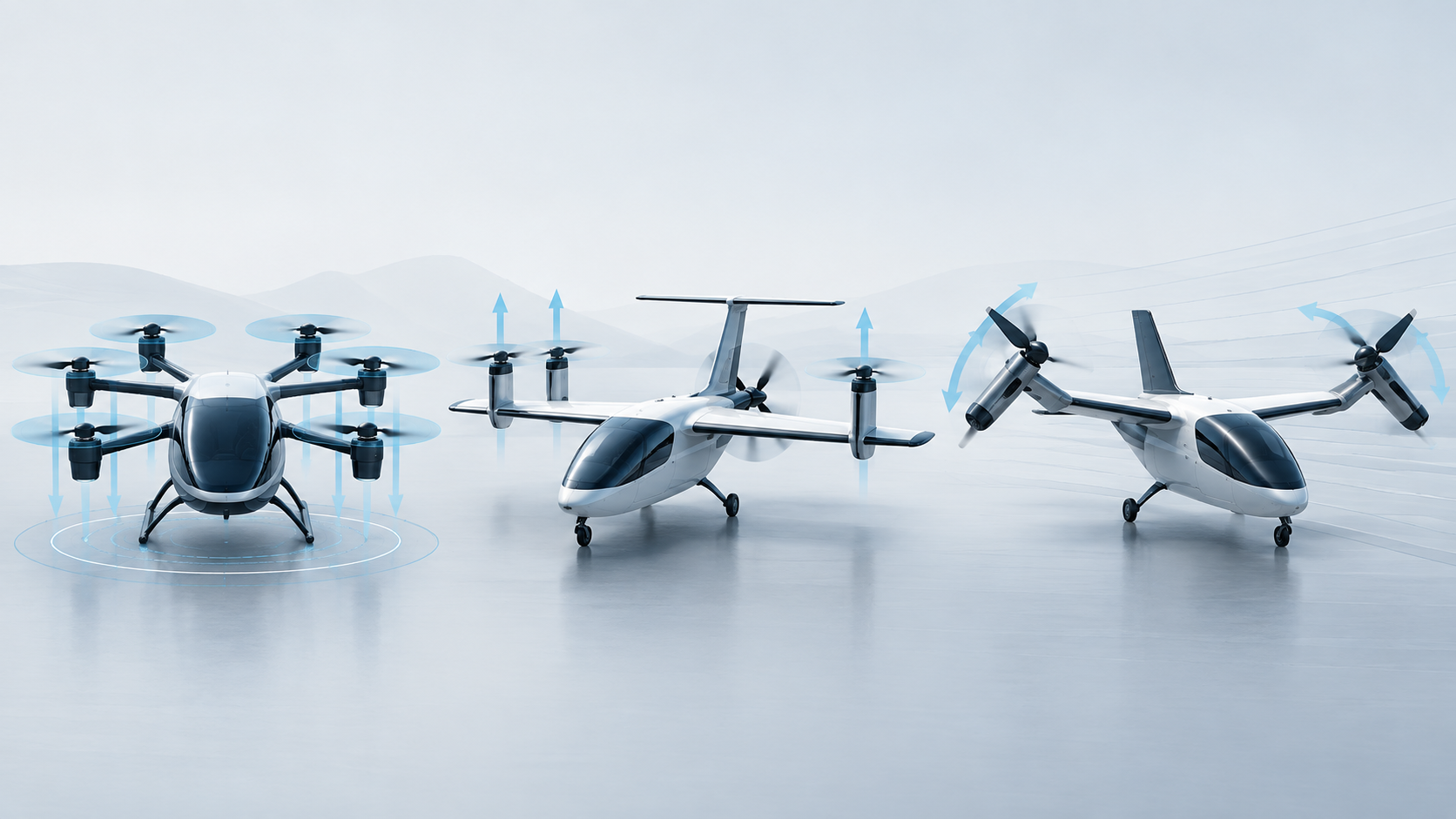
Distributed propulsion can place several motors far from the battery packs. High-voltage distribution then becomes a substantial network rather than a short connection between one battery and one motor. Every branch adds terminations, switching devices, fault-isolation hardware and mechanical supports.
Increasing voltage can reduce copper mass, but the aircraft may need more insulation, greater clearance, different connector geometry or partial-discharge-resistant materials. The optimum voltage is therefore a system result. It depends on transmitted power, route length, ambient pressure, switching waveform, cooling, protection architecture and the probability and consequence of insulation faults.
There is also a maintenance question. A high-voltage connector that passes qualification when new must retain its insulation performance after repeated connection cycles, environmental exposure and vibration. Field inspection methods capable of identifying degradation before an arc or ground fault become valuable as fleets accumulate hours.
Public eVTOL specifications often emphasize motor power, battery energy or aircraft range while leaving insulation coordination largely invisible. That is understandable because detailed high-voltage architecture is usually proprietary. It also means external observers should be cautious about treating a higher bus voltage as an unqualified efficiency advantage.
The stronger evidence will combine altitude, temperature, switching waveform and ageing. Useful disclosures would include partial-discharge margins under representative pressure, motor-winding endurance after thermal cycling, connector and cable qualification, and fault behavior after environmental exposure. A high-voltage architecture earns its aircraft-level benefit only if the conductor-mass savings survive the insulation, cooling, protection and lifetime requirements needed to keep that voltage contained.
NASA — Electrical Insulation for Electrified Aircraft
NASA — altitude testing of magniX electric-propulsion hardware