Pad geometry is only the visible part of a vertiport. Aircraft footprint, charging power, thermal management, parking, passenger flow and airspace determine how much useful operation the site can support.
12,500 lb — upper MTOW in the current FAA EB 105A vertiport scope 350 kW — light-duty vehicle charging level the FAA notes can align with multiple light electric aircraft applications
Vertiport capacity is a system property. Aircraft footprint, stand occupancy, charging acceptance, grid capacity, cooling, passenger flow and airspace can constrain throughput before the landing pad does.
Interoperable charging interfaces, representative aircraft turnaround data, fire and emergency standards, and evidence from multi-aircraft operations showing where the real capacity bottlenecks emerge.
A vertiport can satisfy geometric requirements and still have poor operating capacity. The landing area is only one resource in a chain that includes approach and departure paths, parking, passenger movement, charging, thermal management and the electrical supply behind the charger.
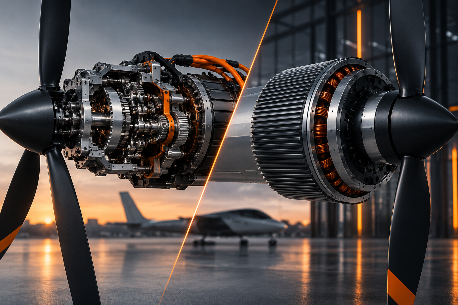
The aircraft therefore cannot be separated from the infrastructure. Propulsion architecture, battery size, ground footprint, downwash and turnaround assumptions determine what the site has to provide and how many movements it can support.
FAA Engineering Brief 105A supplements the agency's heliport design guidance for vertiports. Its scope covers piloted electric VTOL aircraft operating in visual meteorological conditions with a maximum takeoff weight of 12,500 lb or less. That boundary matters: current guidance should not be read as a universal specification for every future autonomous, heavier or differently fueled aircraft.
The protected movement area remains fundamental. Touchdown and liftoff geometry, final approach and takeoff areas, safety areas and obstacle environments have to accommodate the aircraft and its operating characteristics. But those dimensions describe only the flight interface.
An arriving aircraft has to clear the movement area, unload passengers, reach whatever stand or charging position the operating concept requires, complete servicing, board again and return to the departure sequence. If the same physical position is needed for several of those tasks, turnaround time directly consumes landing capacity.
Separating the touchdown area from parking and charging can increase flexibility, but it adds aircraft movement on the ground or in low hover. That creates its own procedures, safety areas and staffing requirements. EASA's Part-IAM material, for example, requires operators to establish standard and contingency procedures for taxiing and ground movement at vertiports and other operating sites.
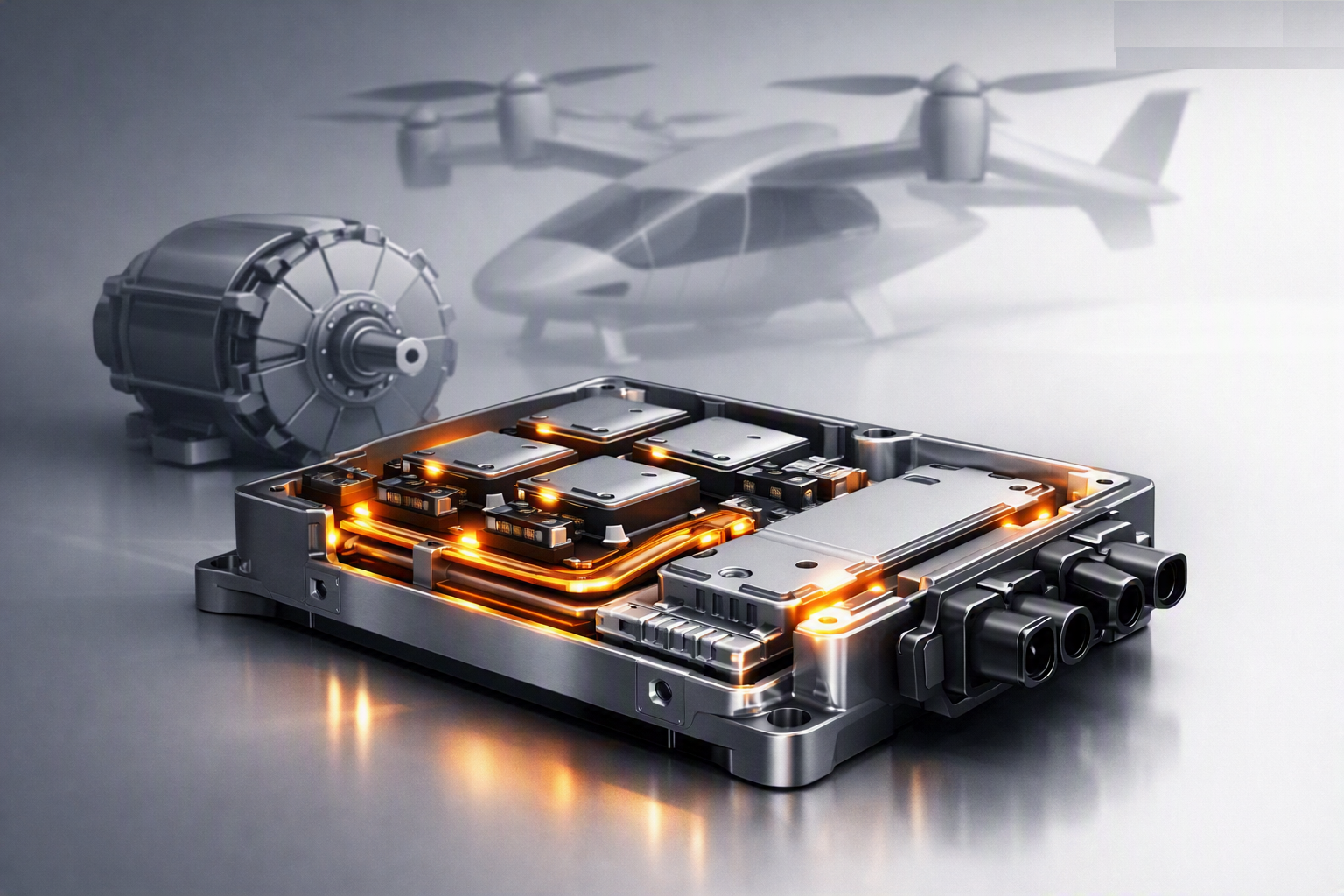
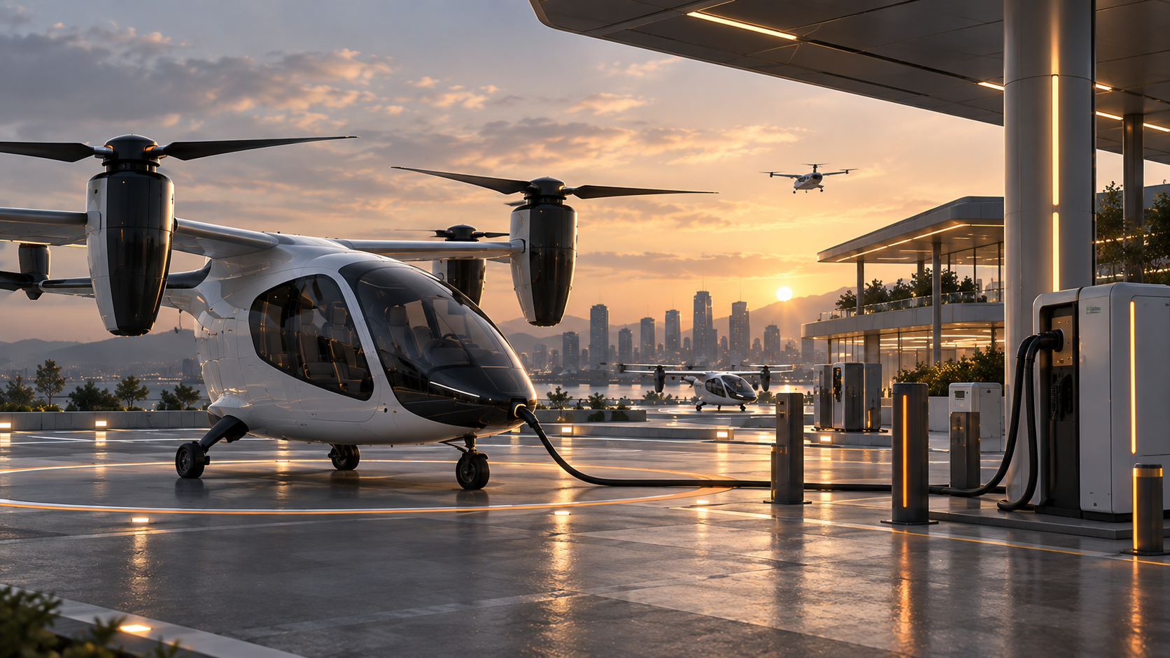
FAA EB 105A describes aviation electrification as an evolving area with relatively few industry-specific standards. It notes that electrical needs vary by aircraft design and manufacturer and that higher-capacity or novel systems may use approaches including fixed charging, mobile charging, stationary battery storage, cable or onboard battery cooling and battery swapping.
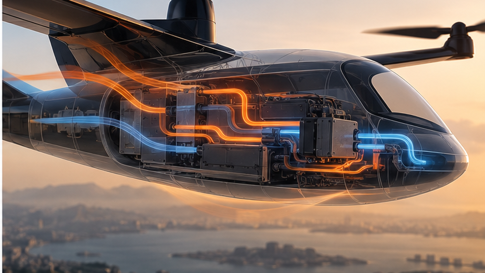
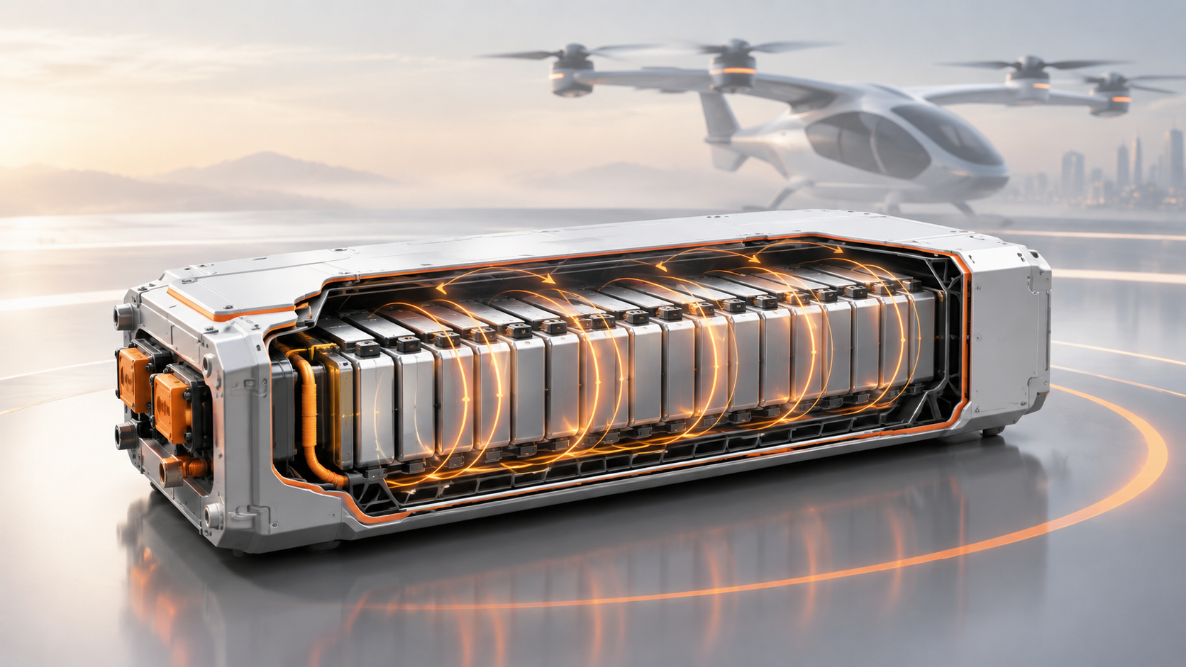
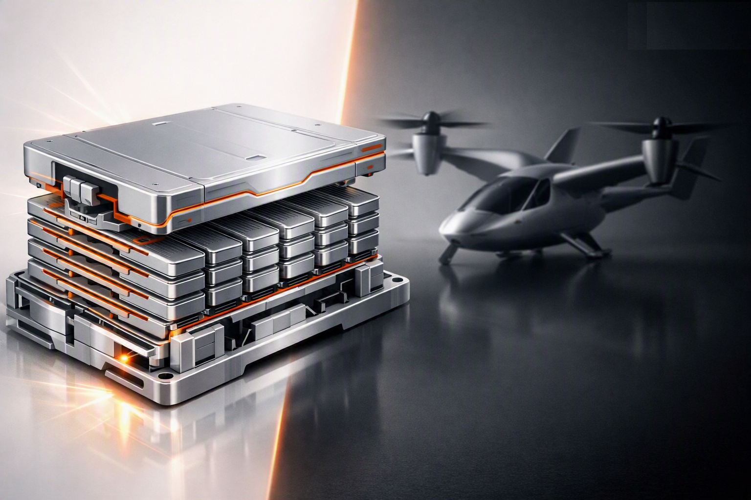
A charger nameplate therefore does not establish turnaround time. The aircraft has to accept the requested power across the relevant state-of-charge and temperature range. The site's electrical connection has to support simultaneous demand, or storage and load management have to bridge the difference. Cooling may continue before, during or after charging depending on the battery system.
The operational quantity is energy restored per turnaround under representative conditions, not the charger's peak kW figure in isolation.
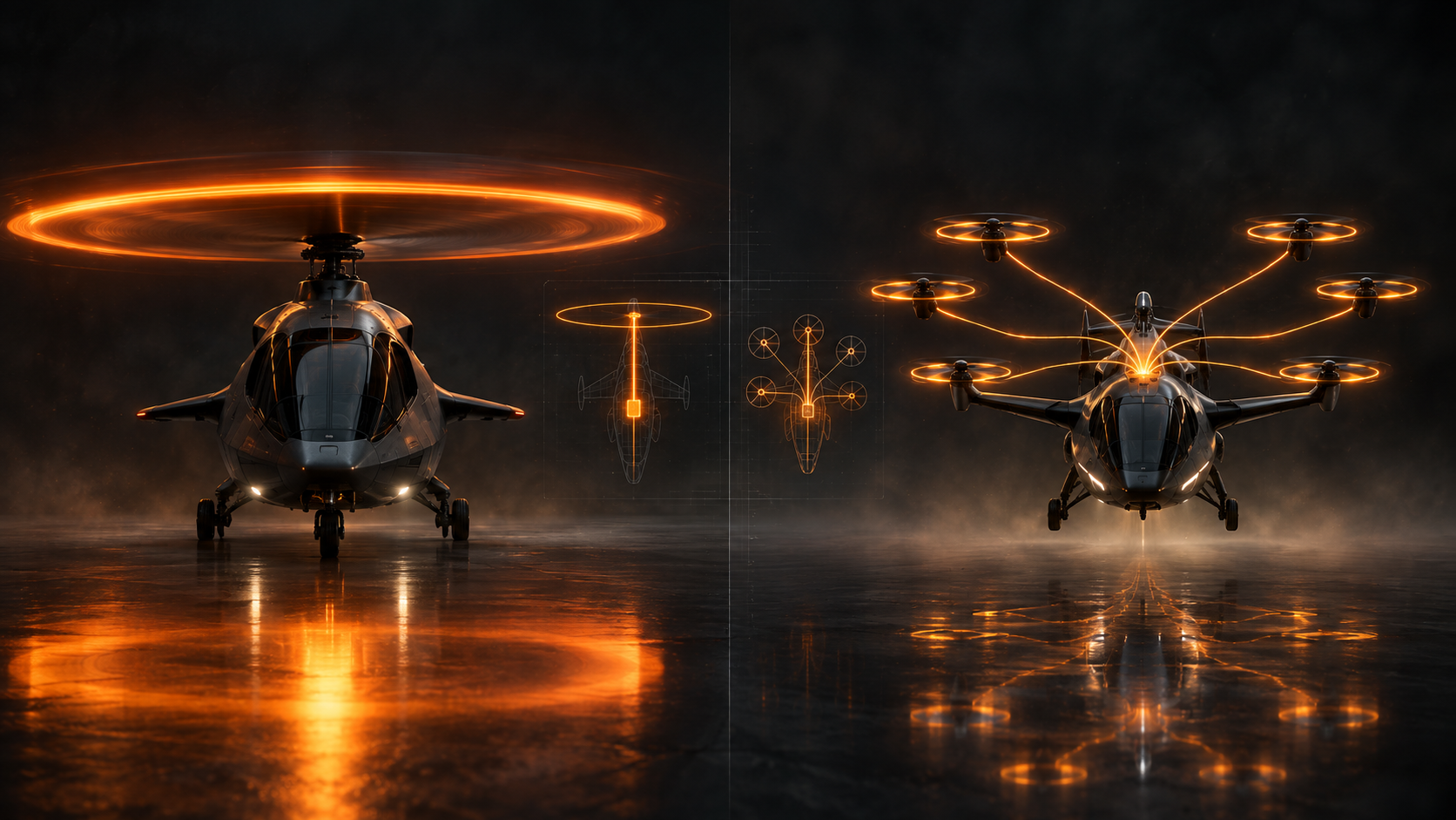
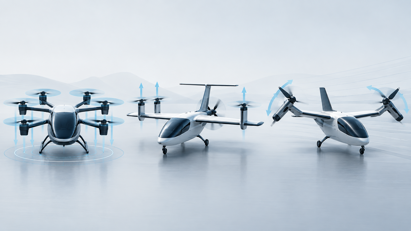
Aircraft on PropulsionWatch already illustrate why one infrastructure assumption is unlikely to fit every program. Joby S4 and Archer Midnight are both piloted passenger eVTOLs but use different distributed-propulsion arrangements. BETA ALIA-250 uses four dedicated lift propellers and a separate cruise pusher. EHang EH216-S is a pilotless multicopter certified in China.
Those differences affect footprint, rotor clearance, ground access, charging interface, passenger path and maintenance access. Infrastructure intended for multiple aircraft types has to accommodate the relevant design envelopes without assuming that a common passenger capacity means a common ground interface.
A high-frequency site needs somewhere for aircraft that are not actively landing or departing. Charging aircraft, spare aircraft and aircraft awaiting passengers all occupy space. If turnaround takes materially longer than the arrival/departure movement, the number of stands can become the practical capacity limit.
This is a queueing problem as much as a geometry problem. A short disruption can propagate if there is no spare stand, no charging margin or no way to resequence aircraft without blocking the movement area.
Electric-aircraft infrastructure has to account for electrical isolation, emergency shutdown, damaged batteries, fire response and access for first responders. The applicable design is not reducible to automotive charging practice because aircraft energy systems, operating environments and evacuation constraints differ.
Where standards remain immature, the correct evidence label is unresolved rather than assumed. Site developers will have to combine aviation guidance with applicable electrical, building and fire requirements while aircraft-specific interfaces continue to mature.
A vertiport's useful capacity can be lower than its ground layout suggests. Arrival and departure procedures, nearby controlled airspace, obstacle constraints, wind limits, visibility and traffic interactions determine how frequently the site can be used.
This is why network-scale research increasingly treats the problem as a coordinated system. NASA's High Density Vertiplex work examines the interaction between aircraft, airspace/flight management and multiple interdependent vertiports rather than optimizing each site in isolation.
The most useful future performance measures will combine the full turnaround: arrival throughput, stand occupancy, energy restored, passenger processing, dispatch reliability and departure capacity under representative weather and traffic conditions.
Pad count is easy to publish. The harder evidence will be repeated operations showing that aircraft, chargers, stands, people, emergency systems and airspace procedures can all sustain the intended movement rate without one interface becoming the persistent bottleneck.
FAA Engineering Brief 105A — Vertiport Design