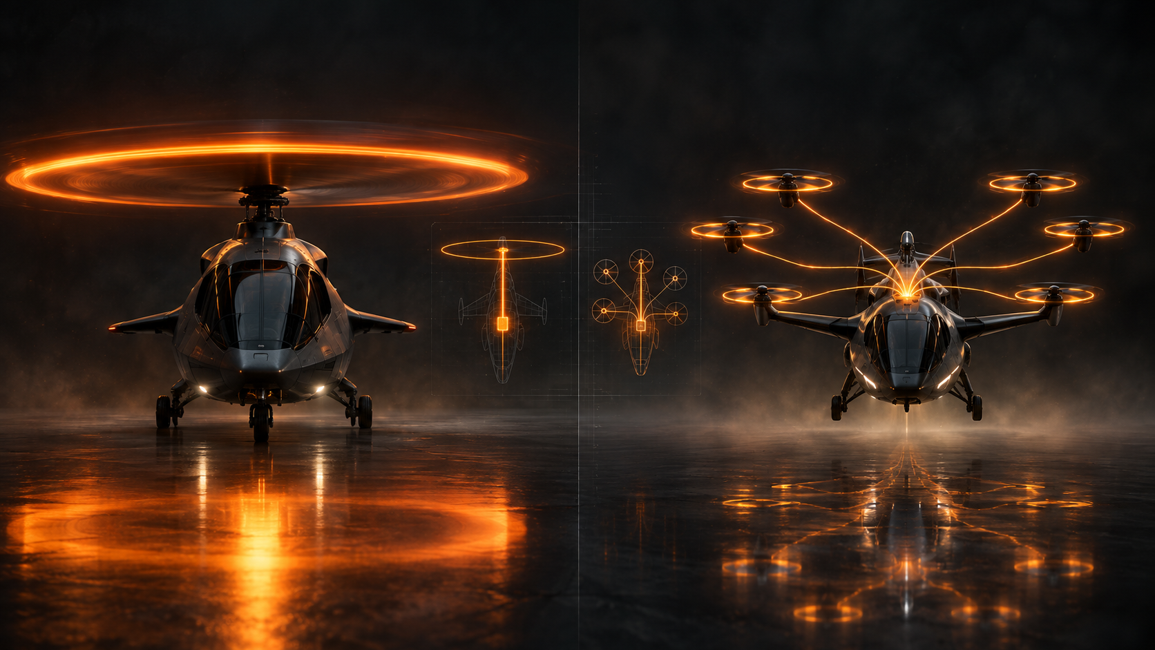
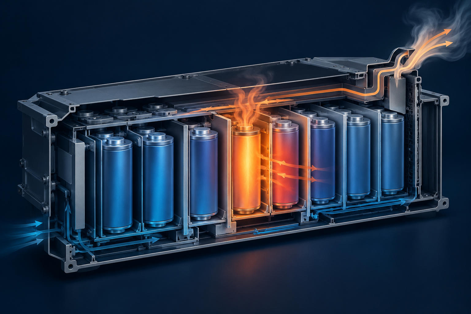
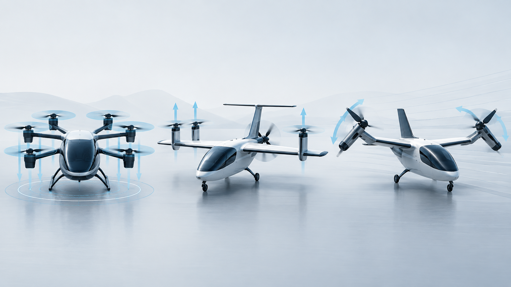
Inverters and motor controllers sit between the battery and motors. Their mass, switching losses, thermal design, insulation and fault tolerance can constrain propulsion even when semiconductor conversion efficiency is high.
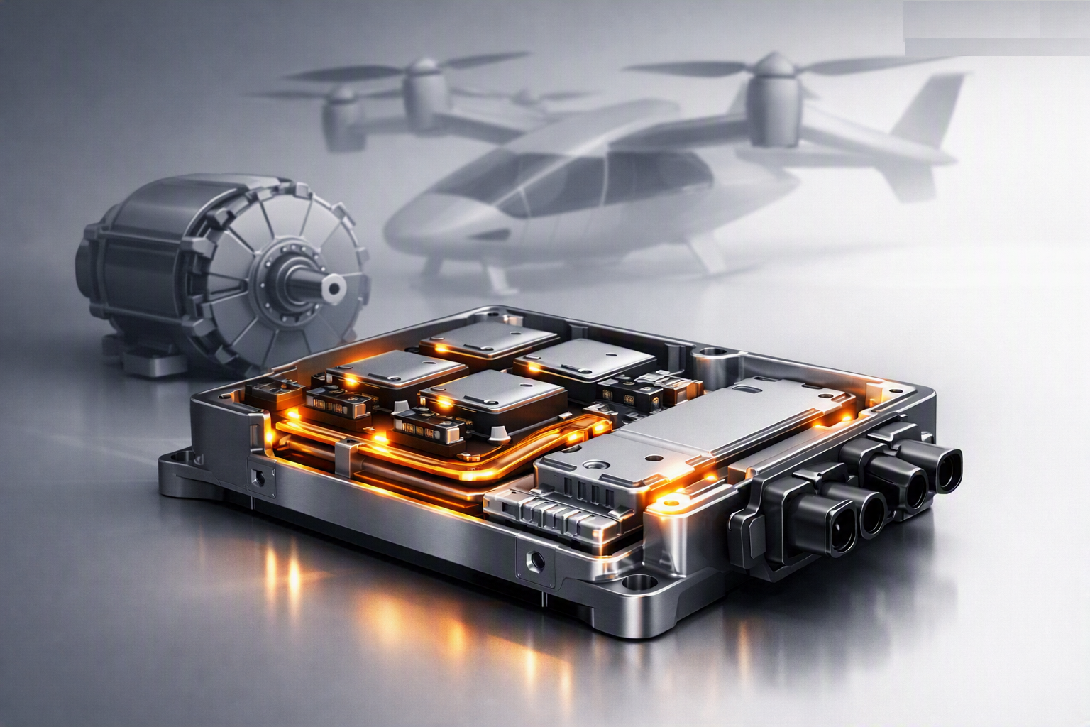
~99% — conversion efficiency of modern SiC MOSFET-based inverters at typical eVTOL bus voltages 400–850V — typical eVTOL powertrain DC bus voltage range ~20 kW/kg — current DC-DC converter power density ~80 kW/kg — industry target power density 10⁻⁹ — Joby's targeted catastrophic motor failure rate, which the feeding electronics must match
Power electronics get far less attention than batteries or motors, but the roughly 20 kW/kg-to-80 kW/kg power-density gap is arguably a bigger open engineering problem right now than battery chemistry — and every kilogram of inverter mass is a kilogram not available for batteries or payload.
Whether gallium nitride (GaN) devices gain further ground on silicon carbide (SiC) for eVTOL-specific high-voltage traction applications, and progress toward closing the power-density gap between today's ~20 kW/kg and the ~80 kW/kg industry target.
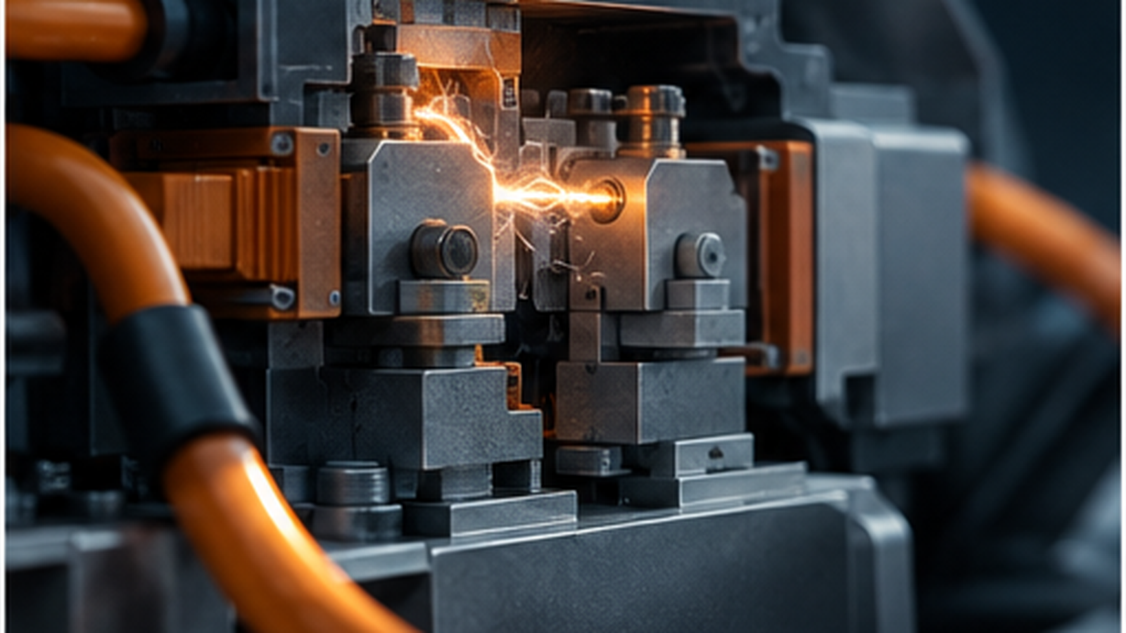
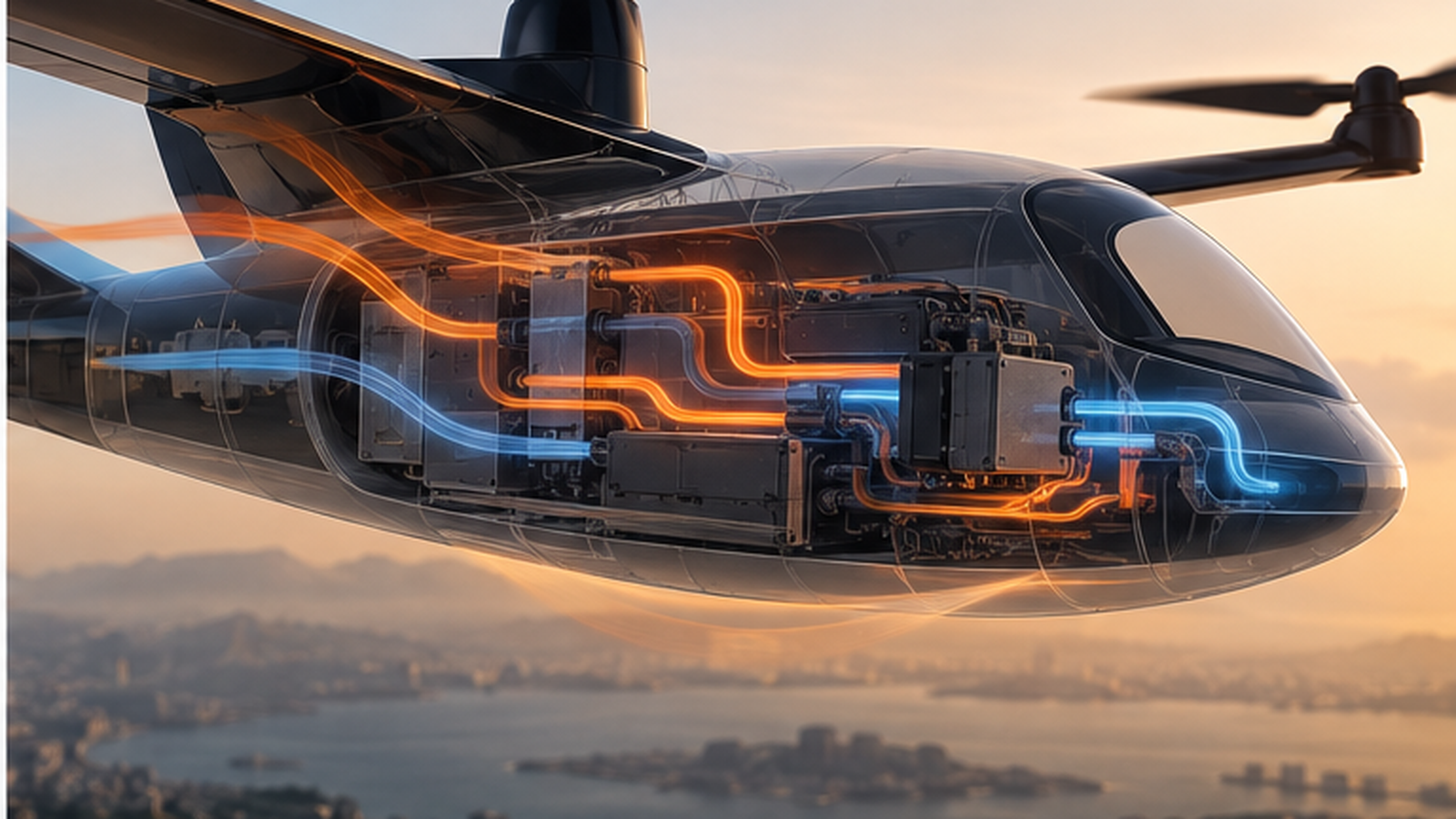
An eVTOL propulsion system does not connect a battery directly to a motor. Between them sits a high-power inverter and its control electronics, converting DC bus power into controlled multi-phase current while managing torque, switching, faults and thermal limits. That hardware is part of the safety-critical propulsion chain, not an accessory to it.
Silicon-carbide power devices can deliver very high conversion efficiency in high-voltage traction inverters, but a peak efficiency figure does not describe the whole aircraft problem. The relevant system questions include efficiency across the mission profile, continuous and transient power capability, cooling mass, electromagnetic compatibility, insulation coordination, fault containment and the mass of duplicated hardware required for redundancy.
That distinction is important when quoting power density. Published kW/kg figures often refer to different boundaries: a semiconductor module, inverter, converter or complete packaged unit may all be described as “power electronics.” Comparisons are only meaningful when voltage, cooling system, continuous-versus-peak rating and included hardware are defined. PropulsionWatch therefore treats isolated power-density targets as directional rather than directly comparable aircraft-level metrics.
A fault-tolerant motor architecture only remains fault tolerant if its inverter, sensing, control and power feeds avoid common failure modes. Joby's dual-winding motor approach, for example, implies electrical independence requirements beyond the windings themselves. More generally, distributed propulsion moves the engineering problem from a single large machine toward coordinated channels whose failures have to be detected, isolated and controlled without producing an unsafe aircraft response.
High voltage adds aviation-specific insulation constraints. Reduced air pressure changes electrical breakdown behavior, while compact packaging raises thermal gradients and partial-discharge concerns. The design problem is therefore not simply choosing SiC instead of silicon: packaging, creepage and clearance, cooling, switching strategy and fault management determine whether the device-level advantage survives at aircraft level.
The useful benchmarks are complete, flight-representative units tested at relevant voltage, temperature, altitude and load, with continuous power and cooling boundaries stated. Until suppliers publish comparable data at that level, claims that one semiconductor technology or a single kW/kg number is the limiting factor should be treated cautiously.
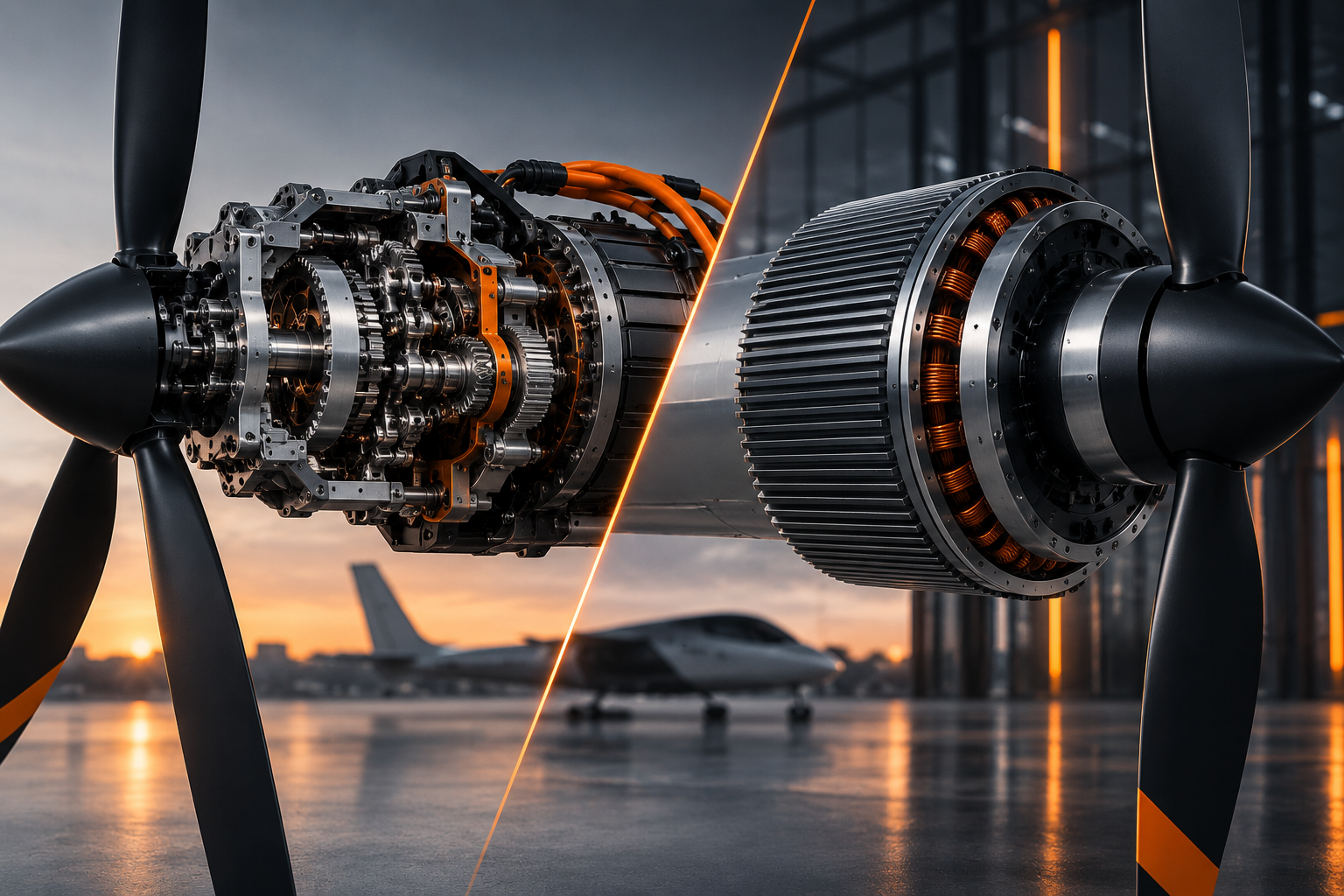
For the related motor-side trade, see Axial Flux vs. Radial Flux.