Fast inverter switching can couple through wiring and parasitic capacitance into battery monitors and avionics. NASA’s X-57 ground tests show why filtering, bonding, routing and receiver immunity must be verified together.
0.8 A — illustrative edge current for 100 pF and 800 V in 100 ns; not continuous leakage 500 V / 2.5 kW — NASA filter-experiment conditions 0.2 kg / 60 µH — NASA experimental choke 3–6 MHz — residual region needing further attenuation against the study’s reference line
Powertrain components share an electromagnetic environment with monitoring, sensing and flight-critical electronics. Installed compatibility affects whether those systems can operate together.
Representative wiring, stated measurement conditions, receiver behavior and installation-level verification alongside component efficiency and mass.
During NASA’s X-57 ground integration, battery-module communications could disappear when the propulsion inverters were active even though power delivery remained good. The fault crossed a system boundary: equipment that could move energy successfully was disturbing the electronics needed to monitor it. NASA’s integration report documents the resulting filter development and investigation of unintended current paths. [1]
Electric propulsion places rapidly switching power electronics near sensors, communication links and low-voltage supplies. Electromagnetic interference (EMI) is the disturbance; electromagnetic compatibility (EMC) is the ability of the installed systems to function together in their intended electromagnetic environment. A complete propulsion specification therefore needs more than motor output, inverter efficiency and thermal limits.
An inverter controls motor current by repeatedly changing the connections between its DC supply and motor phases. The intended result is controlled torque. Each switching transition also produces fast voltage and current changes, with frequency content extending above the switching repetition rate. Ringing adds further spectral peaks. Silicon-carbide devices can support fast transitions, but the chosen gate drive, layout and connected load determine the actual waveform.
Two variables describe much of the initial problem: dv/dt, the rate of voltage change, and di/dt, the rate of current change. A parasitic capacitance is an unintended electrical coupling between nearby conductive parts. It might exist between windings and a motor housing, or across an isolated power supply. Its approximate displacement current is:
i = C × dv/dt
For an illustrative 100 pF coupling and an 800 V transition in 100 ns, the edge current is approximately 0.8 A. This is a short displacement-current pulse, not continuous leakage or a claimed aircraft measurement. Halving the voltage slew rate halves this idealized pulse. Circuit inductance, distributed capacitance and ringing determine the real waveform. TI’s isolated-bias analysis explains the same capacitance-and-slew-rate mechanism. [2]
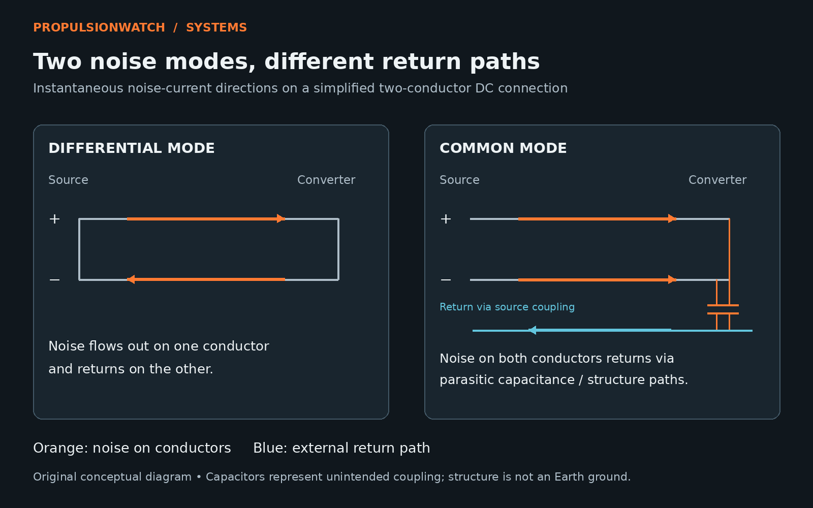
Differential-mode noise flows around the intended conductor loop: out along one conductor and back along the other. On a DC input, it appears between the positive and negative supply conductors. Local decoupling and differential filtering address the impedance encountered by this disturbance.
Common-mode noise moves in the same direction on the conductors relative to a surrounding reference and returns outside that intended pair. Parasitic capacitance, shields, housings and structure can form parts of the return network. In an aircraft, “ground” usually means an electrical reference or bonded structure; it does not require a connection to Earth. These are instantaneous high-frequency current paths, distinct from average propulsion-power flow. [3]
A battery bus can be intentionally isolated from structure at DC while still coupling to it at switching frequencies. An insulation resistance test and an EMC test consequently answer different questions. This extends the insulation discussion: a design can prevent insulation breakdown and still allow enough coupled current to disturb another circuit.
Conducted interference follows electrical connections. Radiated interference couples through electromagnetic fields, with cable geometry influencing both emission and pickup. A disturbance can begin as conducted current, excite a cable, and then couple into another harness. Moving an inverter, changing a motor lead or altering a shield termination can therefore change the result even when the circuit boards remain identical.
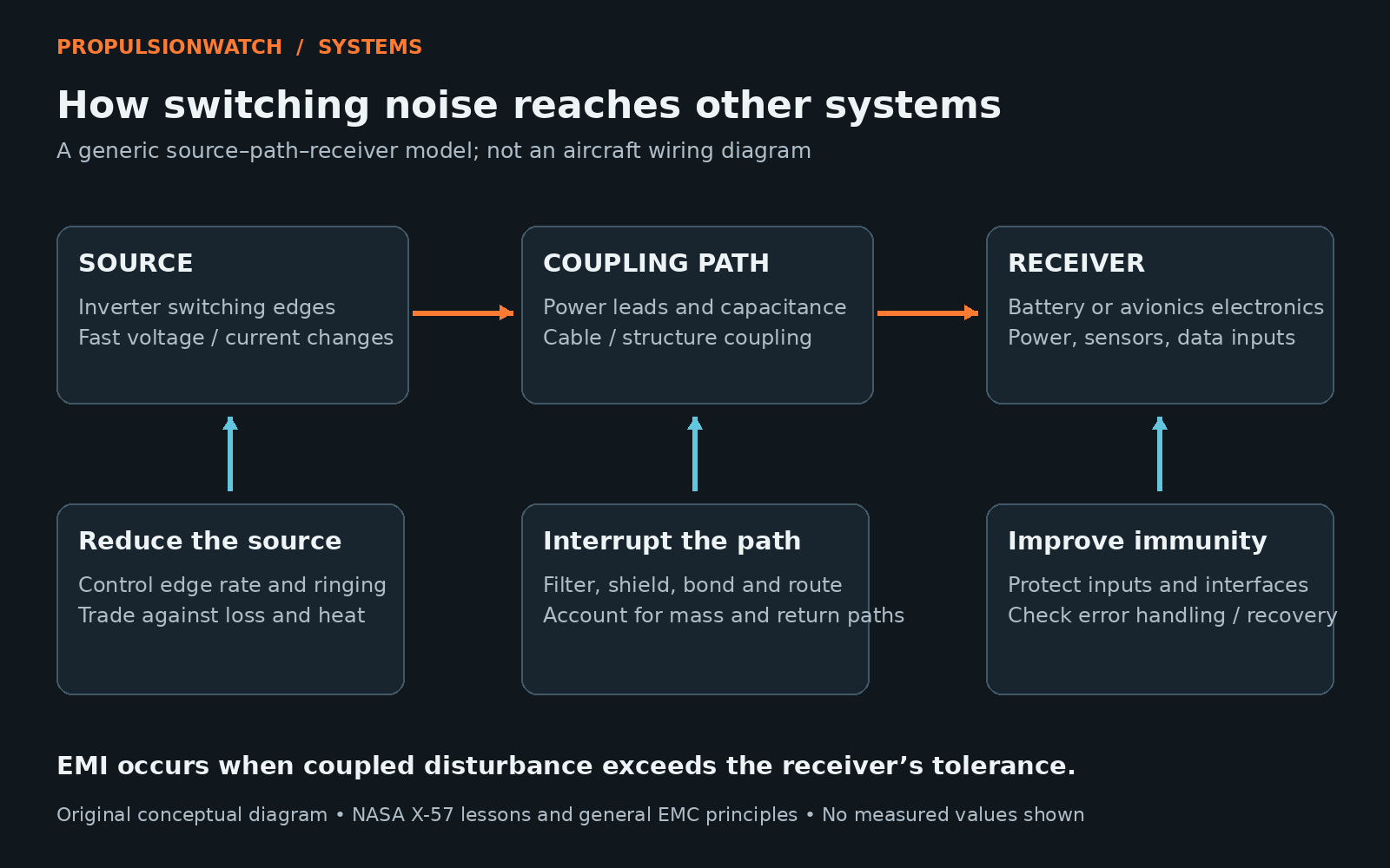
Distributed propulsion multiplies interfaces across wings and booms. A useful integration review traces each source to potential receivers: battery-monitor boards, resolver or encoder interfaces, low-voltage power inputs and communication circuits. The question is whether the resulting disturbance exceeds the relevant receiver’s tolerance in the installed configuration. It is not enough to identify a noisy waveform without tracing its consequence.
NASA’s X-57 lessons include unintended grounding paths and switching noise reaching nearby and remote systems. Those findings are installation evidence from a particular development programme, not proof that every electric aircraft will suffer the same failures. They show why the mounting hardware and wiring belong in the electrical model. [1]
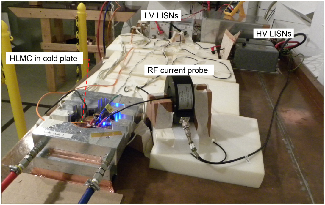
A later NASA study measured emissions from the X-57 high-lift motor controller and evaluated a common-mode LC filter. In the separate filter experiment, a 0.2 kg, 60 µH choke was tested with a 500 V supply and a 2.5 kW motor load. NASA reported roughly 50 dB attenuation from 100 kHz to 2 MHz, while a remaining 3–6 MHz region needed further attenuation against the reference line. [4]
The useful finding is the shape of the result: substantial improvement over one band can coexist with a problem elsewhere. This experiment is not evidence of a universally sufficient filter or a flight-qualified installation. The report’s 14 kW emissions measurements and 2.5 kW filter experiment also have different load conditions and should not be presented as one test.
The source–path–receiver model gives several design levers. Reducing switching-edge speed or ringing can reduce excitation, but may increase switching loss or require changes to the controller. Filtering adds impedance or provides a controlled route for high-frequency current. Its placement matters because a long connection can bypass or degrade the intended high-frequency behavior.
Shielding and bonding need a defined current path. A shield attached through an inductive connection can behave differently from the intended enclosure boundary. Routing supply and return together reduces loop area; separating sensitive wiring from propulsion cabling can reduce coupling. Exact terminations and bonding arrangements require installation analysis, including lightning protection and fault-current considerations. A generic instruction to ground every shield the same way would conceal those dependencies.
Receiver design also matters. Interface filtering, appropriate isolation and tolerance to common-mode transients can improve immunity. Fiber-optic signaling removes an electrical signal connection, but associated power supplies and neighboring copper wiring can still carry disturbances. Error detection and recovery help manage faults; they do not replace demonstrating that safety-critical functions remain available.
PropulsionWatch analysis: the mass comparison should include the installed mitigation, connectors and routing provisions. A lightweight inverter that requires substantial external filtering cannot be compared fairly with a heavier unit whose published boundary includes it. This is the same system-boundary issue discussed in our inverter explainer.
Emissions testing measures what equipment puts onto wiring or into the surrounding field. Susceptibility testing examines its response to an imposed disturbance. Passing one does not establish the other. FAA AC 21-16G recognizes DO-160 environmental qualification procedures and tells installers to compare the equipment’s qualification categories with their specific installation requirements. The AC is guidance, not an aircraft approval. [5]
The X-57 report used selected DO-160G and MIL-STD-461G limits as references; its plots should not be relabelled as aircraft certification pass/fail results. The certification basis and agreed means of compliance determine what a production aircraft must demonstrate.
A credible integration campaign progresses from component measurements to representative cable assemblies, powertrain tests and the installed aircraft. It exercises relevant switching states and system operating modes while monitoring the functions that could be affected. The decisive evidence is a repeatable installation in which propulsion operation does not compromise required sensing, communication or control, with enough information to understand the test boundaries.
Figures 1–2 are original conceptual illustrations by PropulsionWatch. The 0.8 A calculation is illustrative, with assumptions stated above. NASA results are ground-test evidence; architectural implications are engineering analysis.