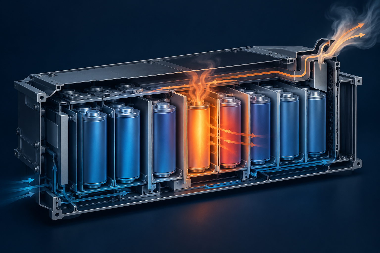
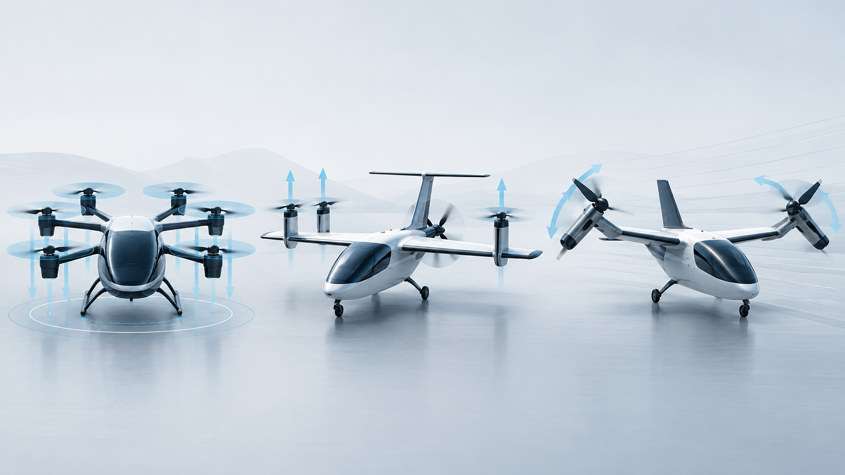
A motor-out case can leave a freely turning propeller, an electrically braked rotor or a seized shaft. What those states mean for drag, heat, isolation and aircraft control—and what feathering or folding can actually change.
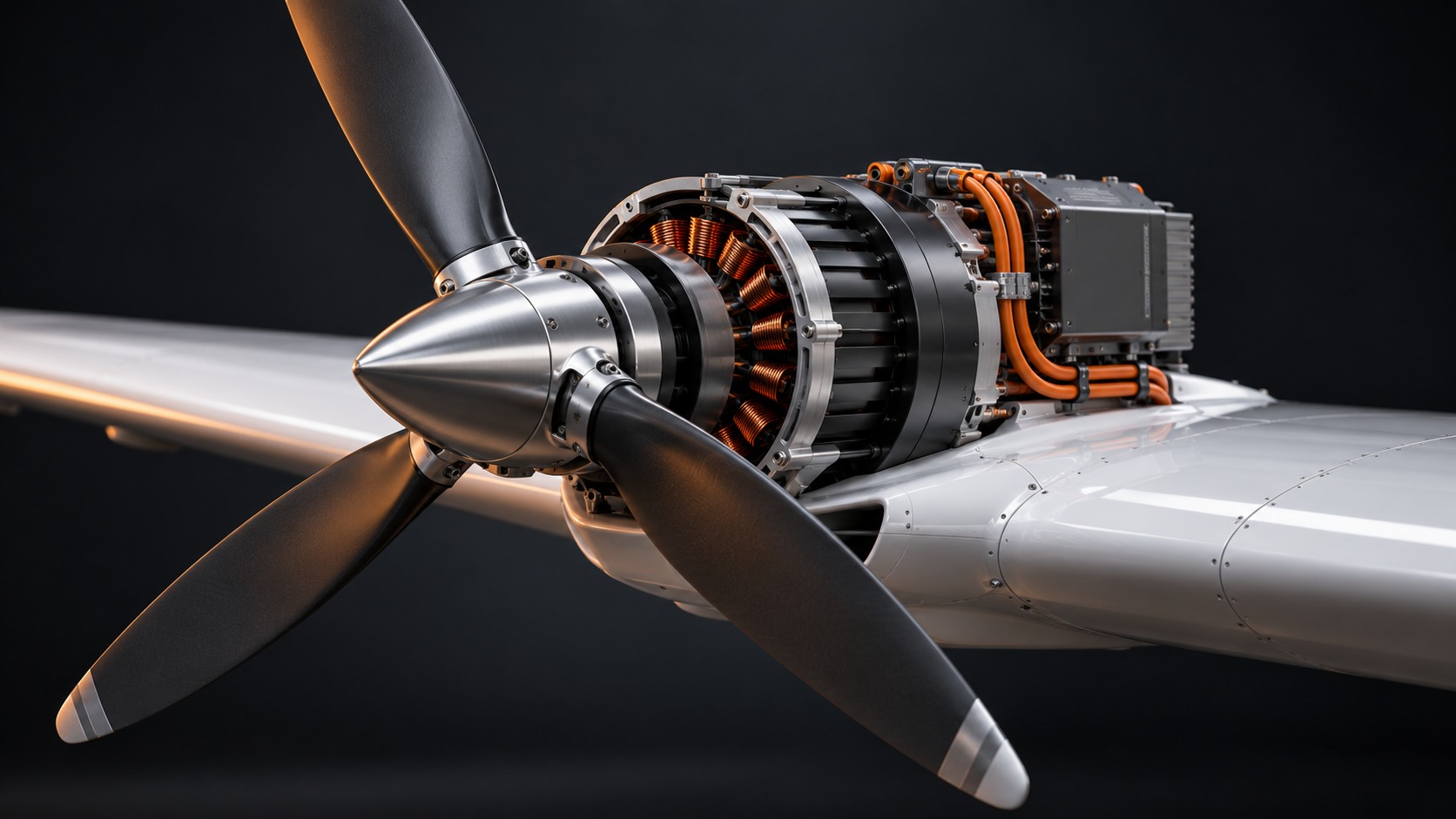
A failed electric propulsion unit can stop producing useful thrust while its propeller keeps turning. Another failure can create an opposing electromagnetic torque. A third can seize the shaft. Calling all three cases “motor-out” hides the different aerodynamic, electrical and structural loads that the aircraft must manage.
The important question is therefore not only how much commanded power disappears. It is what the failed channel does next, for how long, and what remains available to control the aircraft.
Consider a generic direct-drive permanent-magnet motor: an inverter feeds the windings and the rotor drives a propeller. Disabling inverter switching, opening a DC contactor, electrically isolating motor phases and mechanically disconnecting the shaft are different actions. None should be assumed to perform the others.
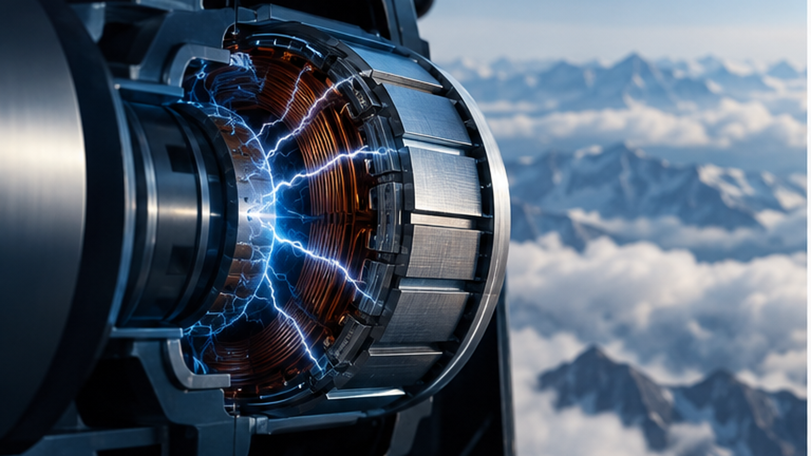
If airflow continues to turn the propeller, the motor rotor can continue to turn with it. The rotor magnets can induce voltage in the windings. Voltage alone does not establish a large fault current: that also requires a conducting path. The actual inverter, protection devices and fault location determine which paths remain.
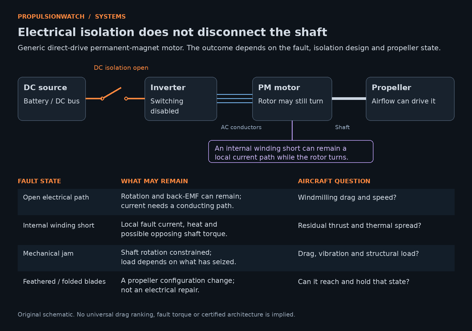
Windmilling means airflow drives the propeller. Its speed and drag depend on blade geometry, pitch, airspeed and the connected drivetrain. A rotating propeller is not necessarily producing useful thrust, charging the battery or being electrically controlled. The power path must be established before describing regeneration.
An internal winding short is different from a deliberately opened electrical path. NASA’s 2026 fault-tolerant motor report describes internal short-circuit testing with the affected module’s power electronics disabled. Rotor magnets still drove current through shorted turns. The work examined electrical, magnetic and thermal separation between motor modules, including the ability of healthy modules to continue operating.
That is research evidence for a particular modular concept. It does not prove that every dual-wound motor isolates internal faults, or that an external contactor can interrupt a closed path inside a winding.
Opposing torque also depends on the machine and fault. A 2026 University of Kentucky research record reports a multi-stage coreless axial-flux permanent-magnet case study in which a three-phase short produced the highest fault current and braking torque of the three fault cases considered. That ranking belongs to the studied topology and conditions; it is not a universal hierarchy for all aircraft motors.
A mechanical seizure constrains shaft rotation through a physical failure. It needs its own drag, vibration and load assessment. An electrically generated braking torque and a mechanically locked shaft are not interchangeable boundary conditions.
An illustrative resisting torque of 50 N·m at 2,000 rpm corresponds to approximately 10.5 kW of absorbed mechanical power, using P = T × 2π × rpm / 60. Those are invented teaching values, not a measured aircraft failure.
This calculation does not identify where every watt becomes heat. Nor does it directly give the aircraft’s extra drag. The propeller’s aerodynamic operating point, drivetrain losses and transient changes must be considered together. Substituting a single “zero-thrust” propeller into an aircraft model can miss those effects.
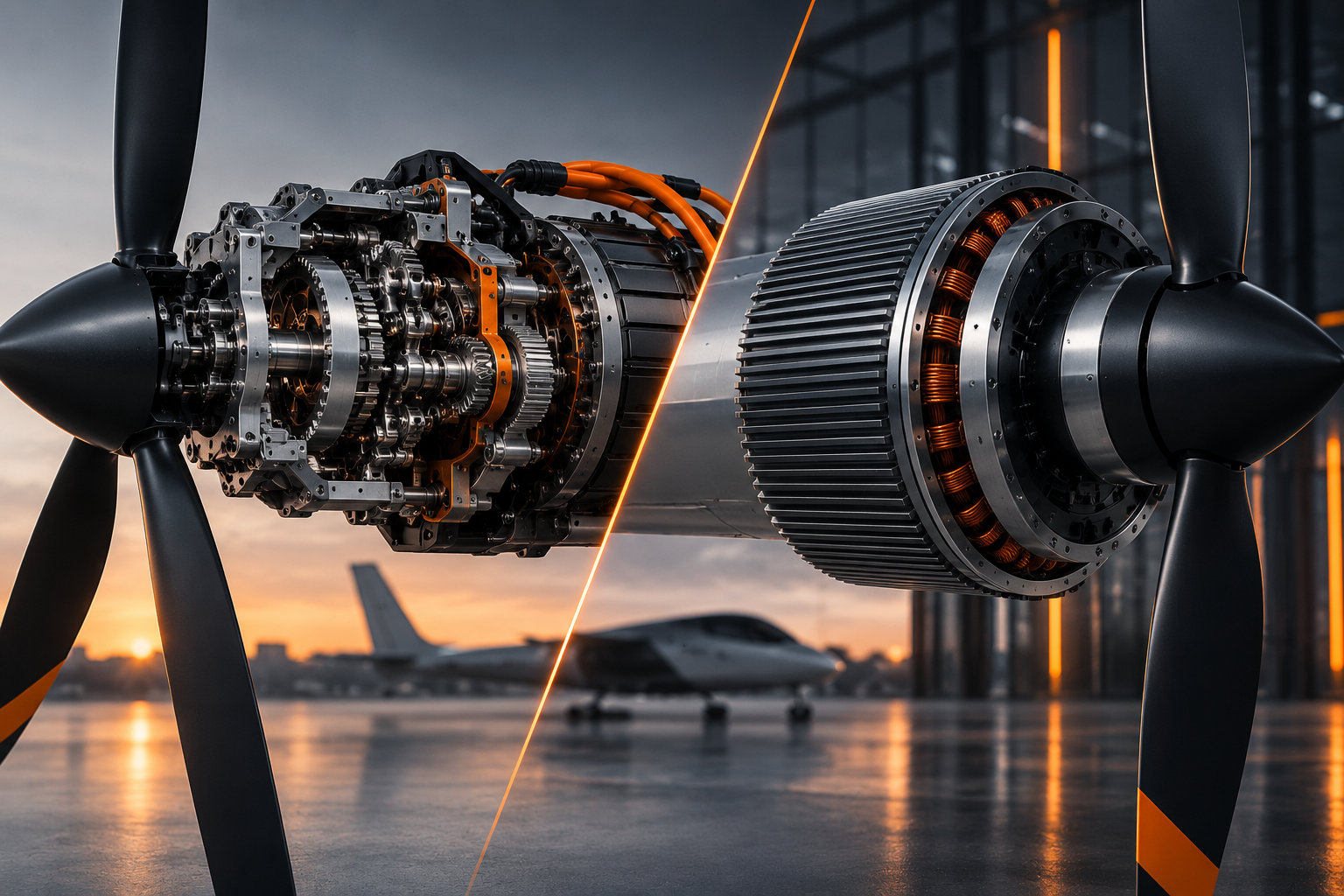
The FAA Airplane Flying Handbook explains feathering as changing blade pitch to streamline an inoperative propeller with the relative airflow and reduce drag. Feathering requires a suitable variable-pitch propeller; a fixed-pitch unit cannot gain that capability through a software command.
Folding is another mechanism. NASA’s X-57 conformal-propeller study compared stowed high-lift blades with deployed alternatives and found substantially less cruise drag than a windmilling configuration. That was a design analysis for a specific high-lift system, not an aircraft-independent drag percentage or proof that folding is the right response to every motor fault.
The distinction in evidence matters: NASA states that X-57 closed before first flight. Its analysis and ground-test results should not be presented as a flight demonstration.
PropulsionWatch analysis: An intended low-drag state is useful only if the system can reach and hold it under the relevant failure. That raises questions about pitch-actuator power, mechanical freedom, sensing and response time. Feathering or folding changes the propeller configuration; it does not repair an internal electrical short.
Residual thrust and drag can change during fault detection, isolation and propeller reconfiguration. For distributed propulsion, that can alter the moments the remaining propulsors and control surfaces must counter. The required response differs between hover, transition and wing-borne cruise; a cruise feathering argument alone does not establish hover capability.
The FAA’s 2021 magni350/magni650 special conditions illustrate the engine-level evidence boundary. They address hazardous effects from permitted continued rotation after shutdown and require representative variable-pitch propeller demonstrations, including feathering and negative-torque operations where applicable. These are applicant-specific special conditions, not a blanket approval or identical checklist for every electric aircraft.
A credible disclosure would identify the initiating fault, remaining electrical paths, shaft torque and speed, propeller state, thermal consequences and time to reach the intended degraded condition. Aircraft-level evidence would then show the resulting forces, moments and available control authority throughout the relevant flight envelope.
That makes this a more precise extension of redundancy beyond rotor count. Related explainers cover DC bus fault clearing and propulsion response in flight control. An isolated bus, a fault-tolerant motor and a manageable failed propeller are connected requirements, each needing its own evidence.
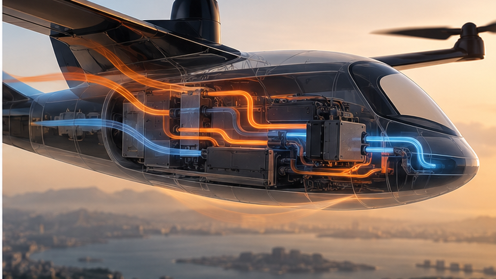
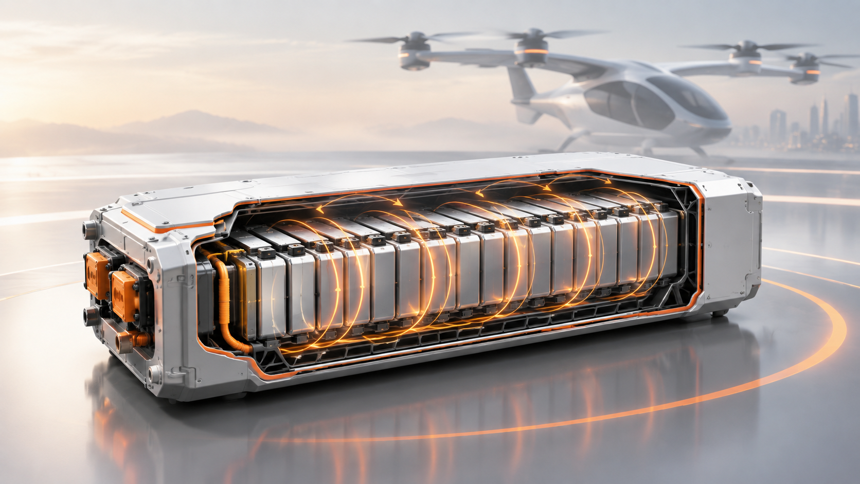
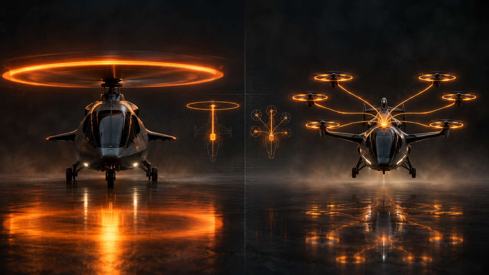
Visuals: Hero is an AI-generated conceptual illustration created for PropulsionWatch, not manufacturer hardware or failure-test evidence. Figure 1 is an original explanatory schematic. Numerical example is illustrative. This article explains engineering distinctions; it is not an aircraft operating procedure.