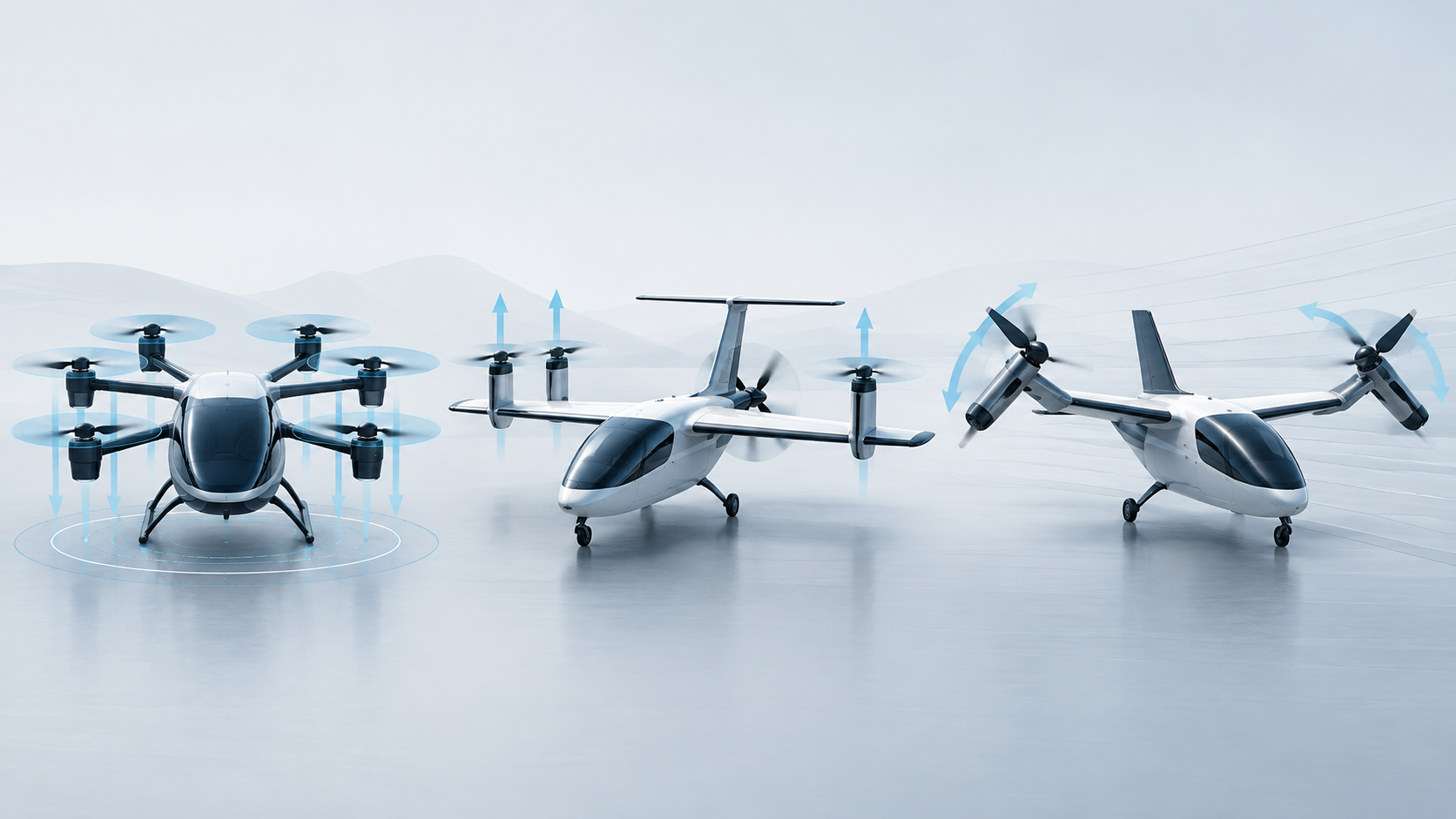
Distributed propellers can change wing lift as well as thrust. A quantitative guide to powered lift margins, spanwise failure effects and the control schedules needed for low-speed flight.
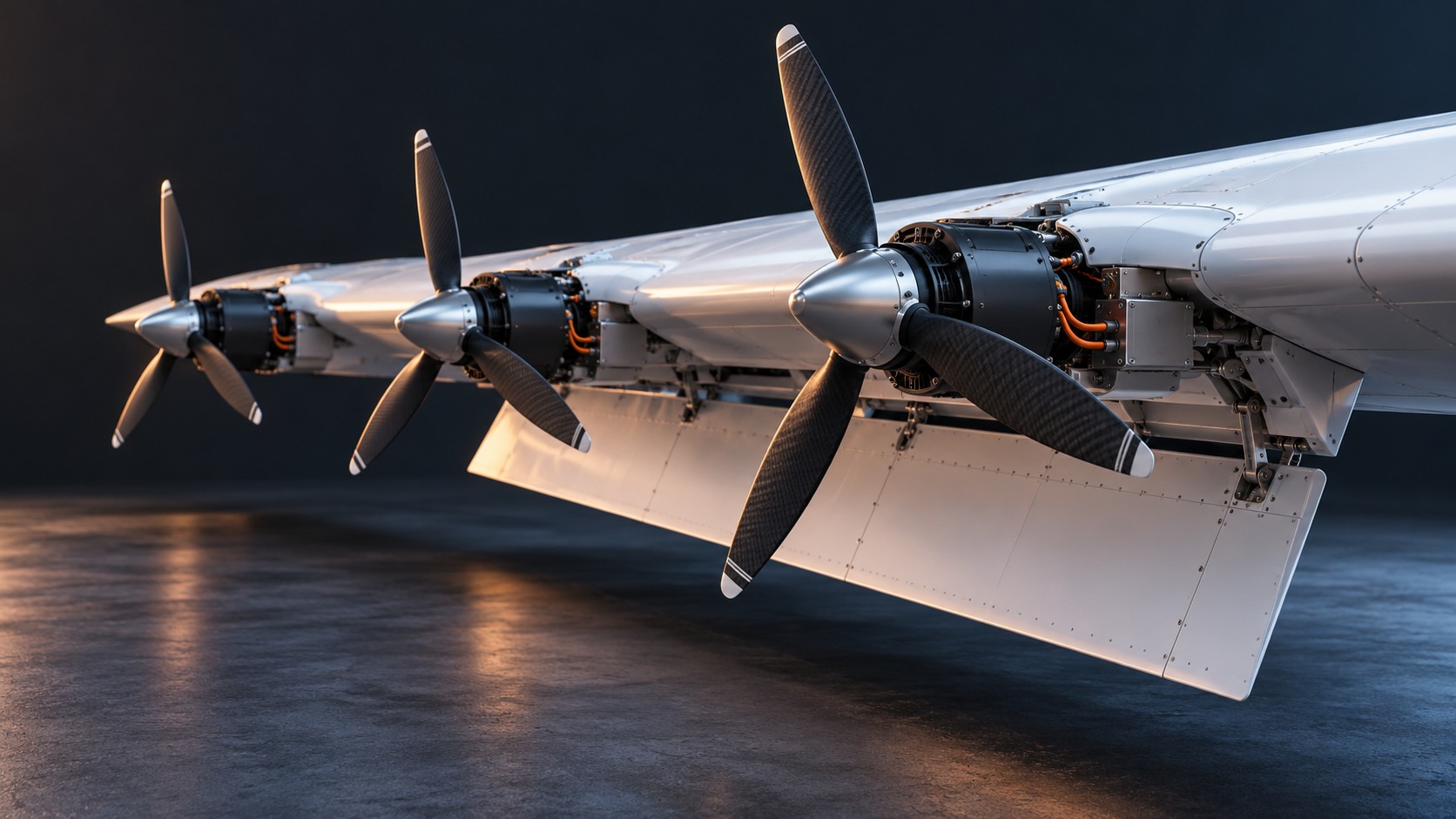
A propeller placed ahead of a wing can change the lift that wing produces. When its slipstream covers the wing and deployed flap, propulsion becomes part of the aircraft's low-speed lifting system. A reduction in power can therefore change thrust and wing lift together.
That coupling is central to distributed blown-lift aircraft. The useful engineering comparison includes the lift remaining after a failure, its distribution across the span and the time available for the aircraft to respond.
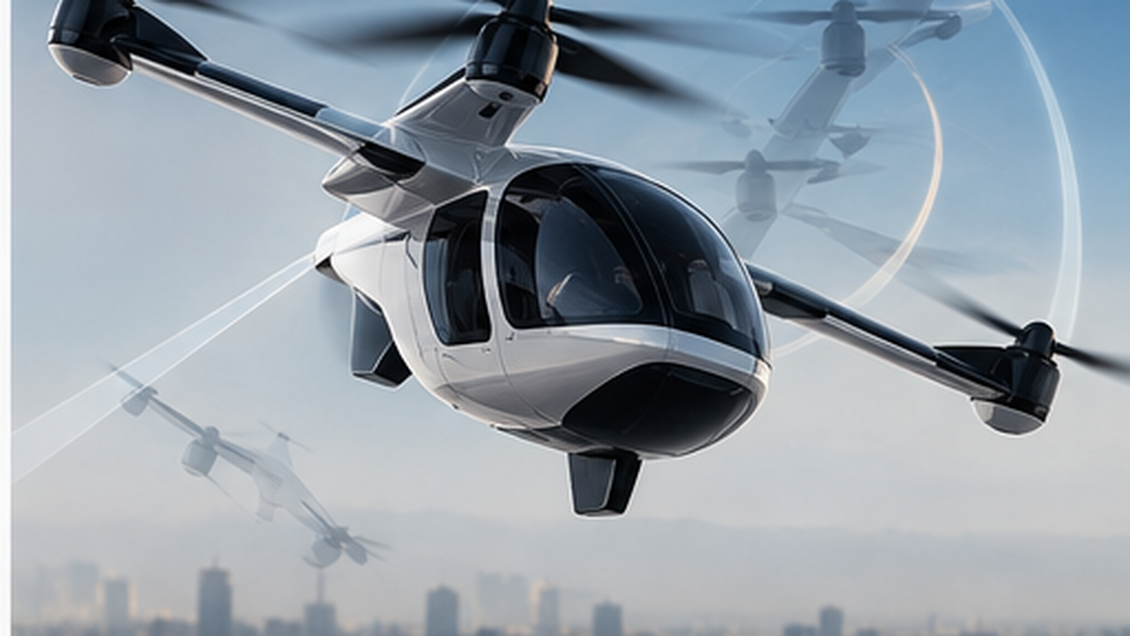
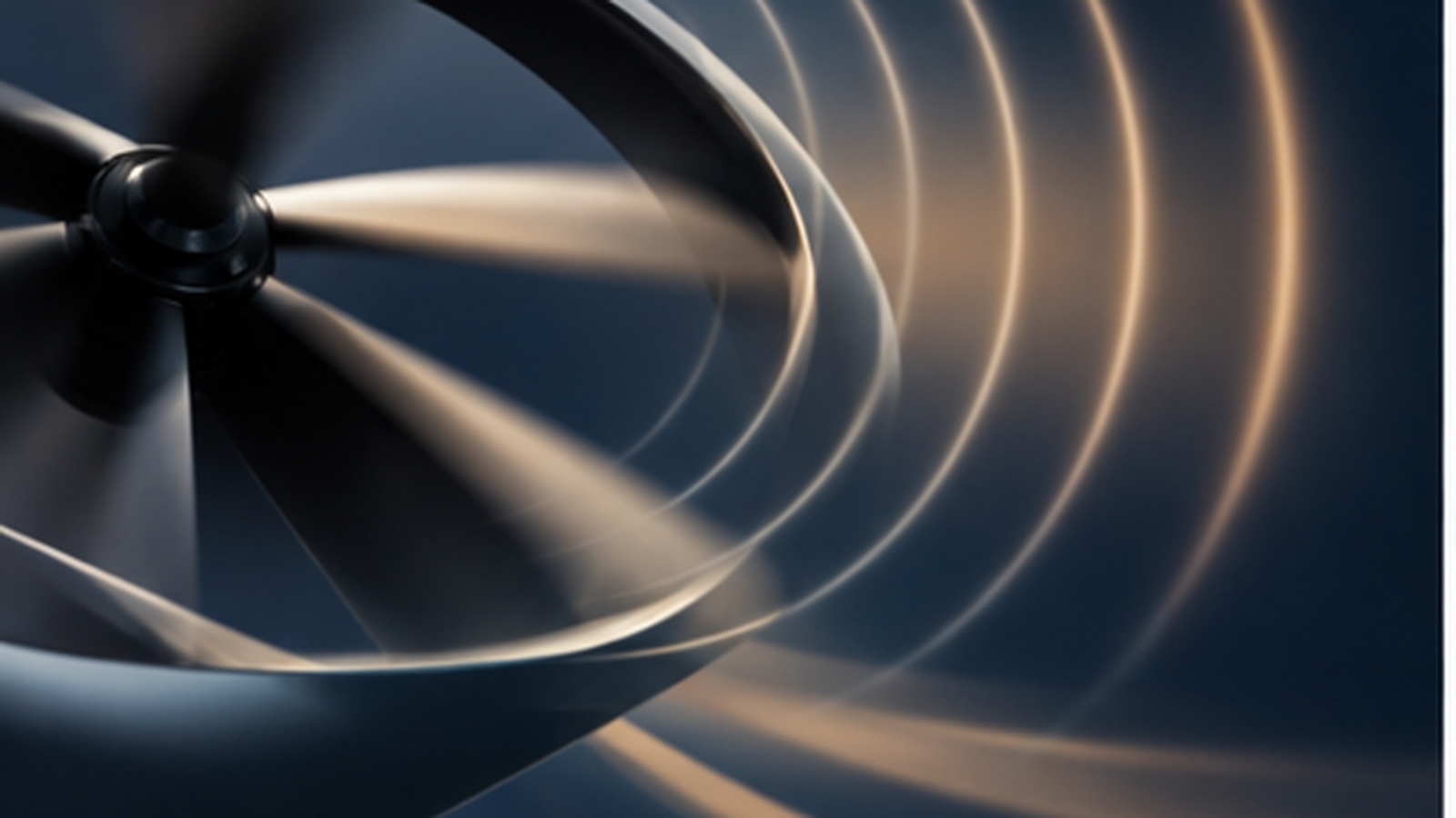
Propellers accelerate air locally. Blowing across a wing raises local dynamic pressure; interaction with the wing and deflected flaps also changes circulation and turns the flow. The complete aircraft force balance includes wing forces and the direction of propeller thrust.
A global notation is Lwing = ½ρV∞² S CL, with CL dependent on angle of attack, flap setting and propeller operating states as well as other conditions. This convention uses freestream speed as a reference. The effect of the nonuniform slipstream is represented in the measured or modelled coefficient; it should not be counted again by simply replacing every part of the wing's airspeed with one higher value.

Consider an invented comparison with weight 30 kN, wing area 20 m² and air density 1.225 kg/m³. If the available wing lift coefficient at one specified powered condition is 4, the steady wing-only lift balance gives approximately 24.7 m/s, or 48 knots. If the available coefficient in another condition is 2, the corresponding speed is 35.0 m/s, or 68 knots.
The ratio is √(4/2), approximately 1.41. This shows the sensitivity of a lift balance to the available coefficient. It is not a transient trajectory, a prediction of any aircraft's stall speeds or an approach instruction. Real limits depend on the actual coefficient maps, propeller states, configuration and total aircraft forces.
Patterson and Borer's NASA approach study treats the extra control freedom provided by high-lift propellers: lift can be changed through blowing as well as angle of attack. A condition with some remaining angle-of-attack margin is not automatically one with ample margin after a major reduction in blowing.
The paper discusses the complete-loss case and the relationship between powered approach conditions and unblown capability. Its X-57 numerical recommendations belong to that research configuration. They cannot be applied to Electra's EL9 or another aircraft by reading a brochure's minimum speed.
PropulsionWatch analysis: The transient matters because a wing can lose a contribution to lift before the aircraft gains appreciable airspeed. Remaining motors, control surfaces and the flight path must be assessed as a coordinated response. A healthy propulsor's maximum rating alone says little about the response if its power supply, thermal limit or actuator dynamics constrain what it can deliver at that moment.
One failed propulsor can remove blowing from a local region. A shared electrical failure can affect several regions at once. The resulting roll, yaw and lift changes depend on the affected positions and the surviving airflow, rather than rotor count alone.
NASA's 2021 X-57 CFD work examined particular motor-failure patterns and found different separation and rolling-moment behaviour. It also reported increased uncertainty where separated flow becomes important. This is configuration-specific analysis, not a universal comparison of electrical bus layouts.
The wing does not become aerodynamically inactive wherever a motor stops. Freestream flow remains, and adjoining slipstreams can interact. A defensible assessment needs spatially resolved forces and moments, plus validated control authority for the relevant failure cases.
NASA's high-lift propeller schedule research developed an airspeed-dependent mode and a fixed-speed mode for particular operating and failure conditions. Its models considered torque, propeller rotational limits and unwanted windmilling. The study illustrates why commanding lift augmentation is more involved than switching motors on before landing.
Air-data errors matter when measured speed helps set blowing. So do power limits and the relationship between lift augmentation and excess thrust: increasing blowing can affect the ability to remain on a desired descent path. The appropriate schedule must be developed from the aircraft's own aerodynamic and propulsion data.
Electra describes an array of electric propellers blowing across the wing and large flaps, with coordinated control of eight motors and flight-control surfaces. The company reduces blowing and retracts flaps for climb and cruise. Its published performance figures are manufacturer positioning, distinct from certified aircraft limits.
Electra's flying EL2 demonstrator and developing EL9 are also different aircraft. The EL9 program dossier keeps that distinction explicit. NASA's X-57 programme closed before first flight; its studies supply research evidence rather than a flight validation of the final high-lift configuration.
The evidence needed for a specific aircraft is a validated lift/thrust/control map across normal and degraded states, including the transient response after loss or reduction of blowing. Related explainers cover propulsion bandwidth, landing-power availability and electrical independence beyond rotor count.
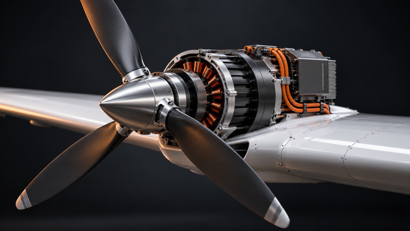
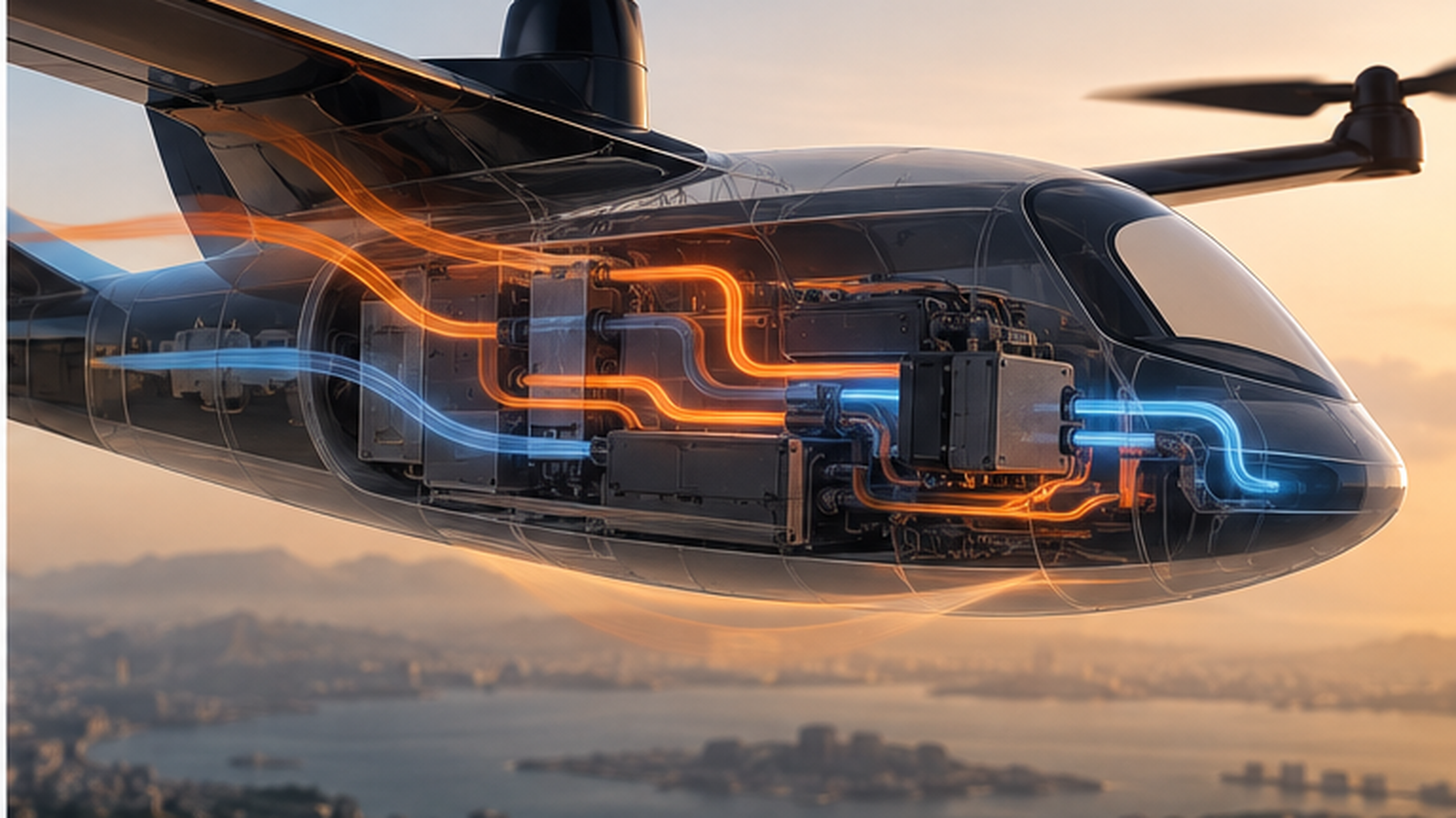
Hero: AI-generated conceptual blown-lift wing illustration created for PropulsionWatch; not manufacturer hardware. Figure 1 and the worked comparison are original explanatory material. This article is engineering context, not an aircraft operating procedure.